23
1730
1761
2040
°3
130
630
1094
1293
H
630
274,5
122
383
627
171
343
641
1062
190
181
214
1
2
3
4
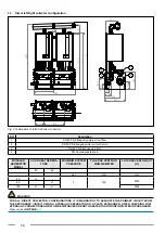
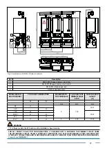
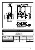
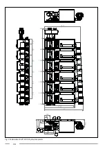
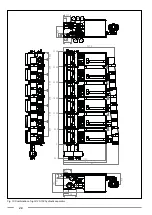
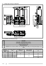
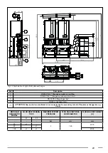
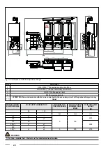
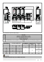
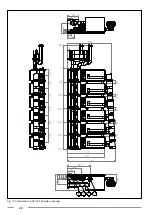
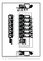
Fig. 12 Combination of right 45-60 plate exchanger
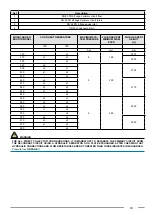
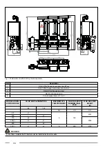
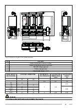
Ref
Description
1
DN 80 PN 6 (**) flanged secondary circuit flow
2
DN 80 PN 6 (**) flanged secondary circuit return
3
DN 50 PN 6 flanged gas inlet
4
DN 50 condensate drain
(**)
ATTENTION: flow and return manifolds to be connected to the secondary circuit of the plate exchanger are op
-
tional
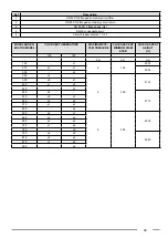
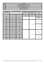
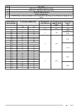
MODULAR
GENERATOR
MODEL
CH KR HEAT GENERA-
TORS
MAXIMUM SYSTEM
PRESSURE
FLUE GAS VENT MINI-
MUM DIAMETER
FLUE GAS VENT HEIGHT
[H]
45
60
-
-
-
bar
mm
mm
45
x1
-
3
160
2075
60
-
x1
105
x1
x1
2095

