97
1.22 Cascade connections
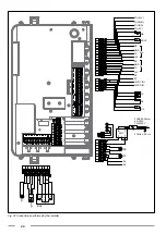
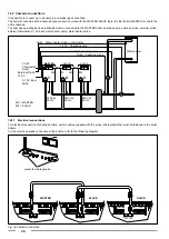
It is possible to connect up to 6 boilers in a cascade-type connection.
The boilers connected with a cascade-type connection work with the MASTER-SLAVE logic: the first boiler (MASTER) controls the
entire cascade.
The cascade operating devices (optional) must be connected to the MASTER boiler: cascade pump, cascade probe, external probe,
ambient thermostat, 0-10V input, water heater pump, water heater probe.
1
MASTER
eco
esc
menu
ok
Lunedi, 24. Settembre 2012
09.37
2
SLAVE
eco
esc
menu
ok
Lunedi, 24. Settembre 2012
09.37
3
SLAVE
eco
esc
menu
ok
Lunedi, 24. Settembre 2012
09.37
BUS
BUS
39-40 Water heater probe or thermostat
13-14 Cascade pump
4-5 Water heater pump
19-20 Cascade probe
Water heater
23-24
Thermostat
Room
External Probe
21-22
0 -10 V input
25-26
M3
M4
M3
M4
230 Vac
50 Hz
230 Vac
50 Hz
230 Vac
50 Hz
M3 = MASTER
M4 = SLAVE
1.22.1 Electrical connections
For electrical connection of cascade boilers, use the cables supplied with the proper cable glands that must be fastened to the boiler
bottom.
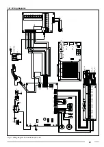
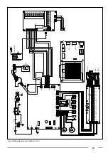
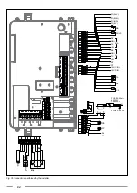
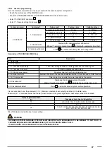
For the electric cascade connection of the boilers, refer to the following diagram:
1
9
2
0
2
1
2
2
2
3
2
4
2
5
2
6
2
7
2
8
2
9
3
8
3
9
4
0
4
1
4
2
4
3
4
4
M3 M4
1
9
2
0
2
1
2
2
2
3
2
4
2
5
2
6
2
7
2
8
2
9
3
8
3
9
4
0
4
1
4
2
4
3
4
4
M3 M4
MASTER M3
SLA
VE M4
MASTER M3
1
9
2
0
2
1
2
2
2
3
2
4
2
5
2
6
2
7
2
8
2
9
3
8
3
9
4
0
4
1
4
2
4
3
4
4
M3 M4
SLA
VE M4
MASTER
SLAVE
SLAVE
preset for cable glands
Fig. 36 Cascade connection
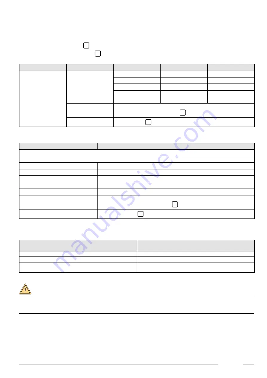
1.22.2 Cascade programming
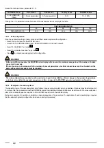
Once the electrical connections are ready, proceed with the cascade system configuration.
• Reach the control panel of the MASTER boiler.
• Access the TECHNICIAN MENU (see TECHNICIAN MENU in the boiler manual).
• Select "6. CASCADE” and press
ok
.
• Select "1. Cascade settings" and press
ok
.
Technician menu
Sub-menu 1
Sub-menu 2
Factory value
Settable values
6. CASCADE
1. Cascade set
1. Cascade switch delay
30 sec
0 ÷ 255 sec
2. Cascade min power
10% min
0 ÷ 100%
3. Single burner power
According to the model
0 ÷ 2550 kW
4. Boiler for DHW
0
0 ÷ 6
5. PI loop time
5 sec
1 ÷ 15 sec
2. Cascade info
Displaying the cascade system information.
Where “*” symbol is present press
ok
to display the parameter time chart.
3. Cascade autodetect
Press
ok
to activate cascade system self-configuration.
Description of TECHNICIAN MENU lines
Ref.
Description
6. CASCADE
6.1. Cascade set
6.1.1. Cascade switch delay
Time interval range between a boiler ignition and the following one.
6.1.2. Cascade min power
Minimum available cascade output.
6.1.3. Single burner power
Maximum heat output of an individual burner.
6.1.4. Boiler for DHW
Number of boilers in the cascade dedicated both to CH function and to DHW function.
6.1.5. PI loop period
Time range to recalculate the power required by the system.
6.2. Cascade info
Displaying the cascade system information.
Where “*” symbol is present press
ok
to display the parameter time chart.
6.3. Cascade autodetect
Press
ok
to activate cascade system self-configuration.
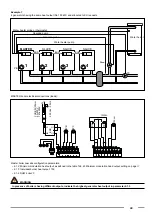
It is recommended to set the parameter [6.1.2. Minimum modulation heat output] as defined in the table below.
Parameter [6.1.3. Individual burner heat output] must be equal to the greatest generator heat output value of the cascade.
Value of parameter 6.1.2
[%]
Cascade system heat configuration
10
45; 60; 90; 105; 120; 205; 240; 325; 360; 480
11
85; 170
16
150; 270; 300; 390; 420; 450; 510; 540; 570; 600; 630; 660;
690; 720; 750; 780; 810; 870; 900
Tab. 43 Minimum modulation head output setting
WARNING
IN CASE OF SYSTEM CASCADE-TYPE INSTALLATION WITH PLATE EXCHANGER IT IS NECESSARY TO SET THE 3.1.5
PARAMETER [BOILER PUMP MINIMUM SPEED] OF THE TECHNICAL MENU TO 30%.
IT MUST BE SET ON ALL MODULES OF THE CASCADE SYSTEM.

