98
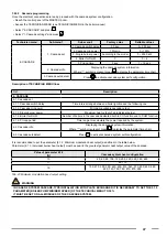
Access the technical menu, parameter 3.1.5:
Technician menu
Sub-menu 1
Sub-menu 2
Factory value
Settable values
3. SYSTEM SET-
TINGS
1. Boiler parameters
5. Pump speed min
15%
15 ÷ 100%
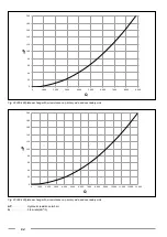
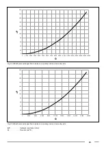
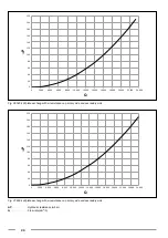
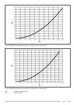
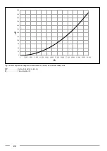
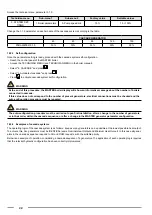
Change the 3.1.5 parameter on each module of the cascade system according to the table:
-
CASCADE GENERATOR
45
60
85
120
150
PARAMETER 3.1.5
30%
30%
30%
30%
30%
1.22.3
Self-configuration
Once the parameter setting is ready, proceed with the cascade system self-configuration.
• Reach the control panel of the MASTER boiler.
• Access the TECHNICIAN MENU (see TECHNICIAN MENU in the boiler manual).
• Select "6. CASCADE” and press
ok
.
• Select “3. Autodetect cascade" and press
ok
.
• Press
ok
to activate cascade system self-configuration.
WARNING
At the end of this procedure, the MASTER boiler display will show an informative message about the number of boilers
connected in cascade.
If this value does not correspond to the number of present generators, electrical connections must be checked and the
auto-configuration procedure must be repeated.
WARNING
The auto-configuration procedure must be carried out upon first installation, after a change in the number of generators
or in their order within the cascade sequence, or after a change in the MASTER generator parameter configuration.
1.22.4
Examples of cascade systems
The operating logic of the cascade system is as follows: keep as many generators on as possible at the lowest possible heat output.
To achieve this, ALL generators must be IDENTICAL (same Nominal Heat Output and Minimum Heat Output). In this case all gener-
ators in the cascade sequence respond to CH and DHW requests, with the suitable priority.
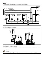
Below is an example of operation, considering a cascade sequence of 4 generators. The application of each operating logic requires
that the relevant hydraulic configuration has been correctly implemented.

