60
Instructions for the installer
Parameter
Settable values
Default values
Notes
P78 Interface back-lighting
switching on
0 ÷ 2
0
0 = standard; 1 = LCD always on
2 = LCD and keys always on
P80 Multifunction relay forcing
0 ÷ 1
0
0 = standard function; 1 = relay
energised
P81 Zone 2 pump relay forcing
0 ÷ 1
0
0 = standard function; 1 = relay
energised
P82 Zone 2 mixing valve forcing
0 ÷ 2
0
0 = standard function; 1 = force
opening; 2 = force closing
P84 Zone 3 pump relay forcing
0 ÷ 1
0
0 = standard function; 1 = relay
energised
P85 Zone 3 mixing valve forcing
0 ÷ 2
0
0 = standard function; 1 = force
opening; 2 = force closing
P87 Zone 4 pump relay forcing
0 ÷ 1
0
0 = standard function; 1 = relay
energised
P88 Zone 4 mixing valve forcing
0 ÷ 2
0
0 = standard function; 1 = force
opening; 2 = force closing
3.14 Filling the system
Once all boiler connections have been completed, CH system can be filled.
The procedure is to be cautiously carried out, following each step:
• Open the bleeding valves on all radiators and verify the boiler automatic valve operation.
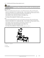
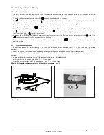
• Gradually open the relevant filler cock, checking any automatic bleeding valves installed in the system properly work (see Fig. 2 Filler cock);
• Close all radiator bleeding valves as soon as water starts coming out.
• Check on boiler display that water pressure reaches the 1÷1.3 bar reading.
• Shut the filler cock and bleed any air out again, by opening the air bleeding valves on radiators.
• Start the boiler and bring the system to working temperature, stop the pump, and repeat air bleeding procedure.
• Allow the system to cool and restore water pressure to 1÷1.3 bars.
WARNING
As for water treating in the domestic heating systems in order to optimise efficiency and safety, ensure a long life, trouble-free
operation of auxiliary equipment, minimise power consumption, thereby integrating the standards and rules in force in the
country of installation, it is recommended to use specific products suitable for multi-metal heating systems.
WARNING
Pressure sensor will not electrically enable the burner ignition when water pressure is below 0.4 bar (this parameter can be edited
by qualified professional staff).
Water pressure in the CH system must not be lower than 1 bar. In case it is not so, fill the system with water (see
Shut-down due to
low water pressure
on page
27
).
The procedure is to be followed while the system is cold.
Digital pressure gauge is used to read pressure inside the heating circuit.
Summary of Contents for ITACA KB 24
Page 42: ...42 Instructions for the installer Fig 6 Paper template ...
Page 79: ...79 ...


