30
In order to install the boiler proceed as follows:
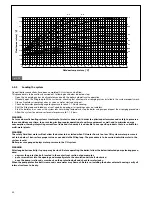
- affix the template (pic. 13) to the wall;
- drill two 1 mm Ø holes in the wall to accommodate the boiler support bracket wall plugs;
- arrange air intake/flue gas system path in the wall as needed;
- secure boiler support bracket to the wall by means of the wall plugs supplied with the boiler;
- position gas supply network coupling (G), water mains supply coupling (CWI, only in KC model), DHW flow coupling (DHW, only
in KC model), CH flow coupling (F), CH return coupling (R) and condensate drain coupling (S), as shown on the template (refer to
its lower area);
- provide a system for relieving the 3-bar safety valve of metal construction (SV in pic. 5);
- position the boiler to the supporting bracket on the wall;
- connect the boiler to network pipes by means of the coupling kit supplied with the boiler (refer to 4.5.3 and 4.5.4 paragraphs);
- connect the boiler to pipe for condensate discharge (refer to 4.4.4. paragraph);
- connect the boiler to the system for relieving the 3-bar safety valve;
- connect the boiler to the air intake and flue gas exhaust system (refer to 4.5.1. paragraph);
- connect electric power supply, ambient thermostat (when available) and other available accessories (refer to 4.5.5. paragraph).
4.4.3 Gas main connection
The gas installation should be in accordance with the relevant standards. In GB this is BS 6891.
Gas supply pipe cross-section must be equal or greater than boiler gas pipe.
Cross-section gas pipe size calculation depends on its length, layout pattern, gas flow rate. Gas pipe size is to be dimensioned
accordingly.
Comply with installation standards BS 6891 enforced in the installation country which are considered as fully transcribed in this
booklet.
Remember that before operating an indoor gas distribution system and before connecting it to a meter, it must be
checked for leaks.
Adhere to the following leak test instructions:
- leak test is to be carried out before pipes are covered;
- leak test is not to be carried out employing flammable gas: use air or nitrogen for this purpose;
- when gas is already in the pipes supplying the boiler, leak testing by naked flame is forbidden, use specific
products available on the market.
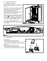
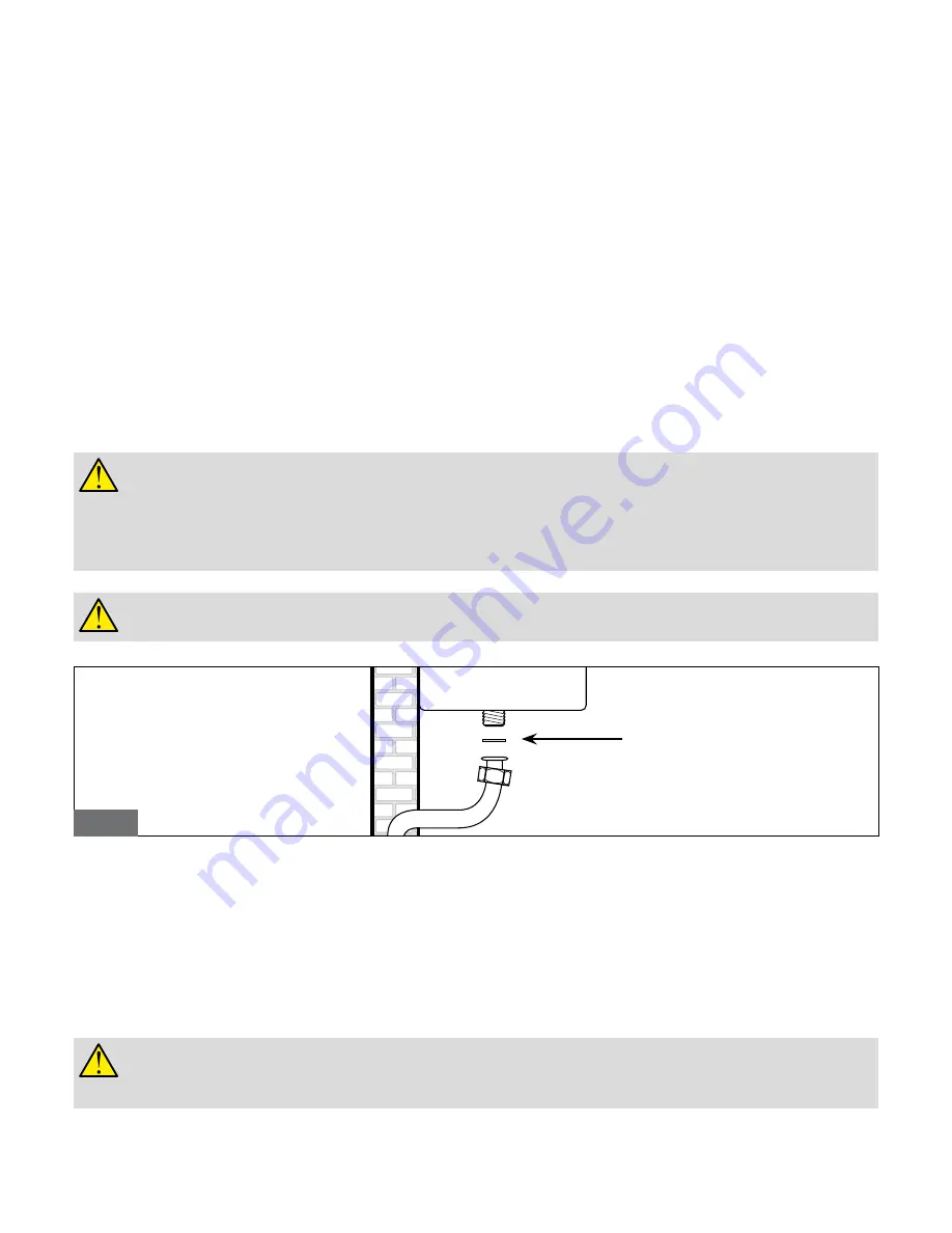
When connecting the boiler to gas supply network, install an appropriately sized and made gasket (pic. 18).
The boiler gas inlet thread configuration is not appropriate for hemp, plastic tape or similarly made gaskets.
4.4.4
Hydraulic connections
Prior to installing the boiler, the hydraulic system is to be cleaned in order to remove impurities; they could be present in system compo-
nents and damage the pump and the heat exchanger (refer to 4.4. paragraph).
CENTRAL HEATING
CH flow and CH return pipes must be connected to the relevant 3/4” F and R couplings on the boiler (pic. 5).
When calculating the cross section of CH system pipes, bear in mind load losses induced by radiators, thermostatic valves, radiator gate
valves, and the configuration of the system itself.
It is advisable to convey the discharge flow of boiler safety valve to the sewer system. Should the above precaution not
be implemented and the safety valve be activated, boiler room flooding may occur.
Manufacturer shall not be held responsible for any damage resulting as failure in observing the above mentioned
technical precaution.
pic.18
Gasket
Summary of Contents for Tahiti Condensing 24 kW Combi (KC)
Page 46: ...46 7 Spare part list pic 33 KC model ...
Page 47: ...47 pic 34 KR model ...
Page 53: ...53 ...
Page 54: ...54 ...
Page 55: ......


