background image

8.-

12

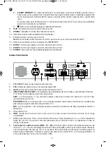
/RPT-MEMORY

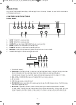
: in playback mode, a short press of this button begins and pauses playback. 

A long press of this button allows the playback mode to be selected among: random playback 
(RAN), repeat one track (SIN), repeat folders (FOL), repeat all (ALL. 

In radio mode, this button lets you change successively among the stations saved during automatic 
tuning 

9.-

q

: player module on/off button. 

8.-

CLIP

: LED signal saturation indicator. 

9.-

SIGNAL

: LED signal presence indicator. 

10.- LED power indicator. 

11.- Aux input, 3.5 mm jack connector. 

Note

: this frontal aux input is the same as the one on the rear panel (AUX). 

12.- Aux input or USB/SD/MP3 player selector. 

13.-

ZONE 1

: control that regulates the output volume of zone 1.


14.-

ZONE 2

: control that regulates the output volume of zone 2. 

15.-

POWER

: amplifier on/off switch. 


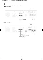
REAR PANEL


1.-

115 V/230 V

: power supply voltage selector. 

2.-

FM

: antenna input for the digital FM tuner. 

3.-

GAIN

: 100 V line input signal level control. 

4,-

LINE/PHANTOM 24 V/MIC

: input and 24 V phantom power supply sensitivity switches. These switches 

have three positions: 

LINE

: in this position, line level audio sources can be connected to the inputs: CD players, etc. 

PHANTOM 24 V

: in this position, electret condenser microphones that require 24 V phantom power can 

be connected to the inputs. 

MIC

: in this position, the inputs can be connected to low impedance 30-600 Ω dynamic microphones. 

5.-

AC power supply. 

6.-

GND

: earth screw, to be used if the mains does not have one incorporated. 

7.-

Loudspeaker output. For connecting loudspeakers in 4 Ω  low  impedance  and in  high  impedance     
100/70 V lines. Connect the loudspeaker line between the COM terminal and the impedance or line in 
the required volts (V). 

8.-

Zone output terminals (COM - Z1 - Z2)

: terminals to connect the loudspeaker lines of zones 1 and 2. 

With the zone selection terminals only loudspeakers with 100 V line transformer must be used. The total 
connected power in loudspeakers must not exceed the power of the amplifier. Connect the positive of 
each zone to the corresponding terminal Z1 and Z2 and that common to all the zones to the COM 
terminals.

115 V

230 V

COM

FM ANT

PRIORITY 100 V INPUT

GND

R

L

R

L

GAIN

COM

Z1

Z2

MA-91RUZ

PA AMPLIFIER

90 W RMS

CAUTION: SHOCK HAZARD - DO NOT OPEN

RISK OF FIRE-REPLACE FUSE AS MARKED

CAUTION

RISK OF ELECTRIC SHOCK

DO NOT OPEN

POWER CONSUMPTION: 125 W

~ 110-120 V AC. 50/60 Hz FUSE: T2AL 250 V 

~ 220-240 V AC. 50/60 Hz FUSE: T1AL 250 V 

COM

4 Ω

70 V

100 V

CLASS II WIRING

PRIORITY

INPUT 1

INPUT 2

LINE OUT

AUX

LINE

MIC

PHANTOM

+24 V

LINE

MIC

PHANTOM

+24 V

1

6

7

8

9

10

12

11

5

2

3

4

- 3 -

EN

MA-91RUZ_MANUAL_(EN_ES_FR_PT)_A5c_20200506-2020.qxp_Maquetación 1  6/5/20  11:38  Página 3

Summary of Contents for MA-91RUZ

Page 1: ...A USB SD MP3 FM AMPLIFICATEUR DE SONORISATION USB SD MP3 FM AMPLIFICADOR DE MEGAFONIA USB SD MP3 FM INSTRUCTION MANUAL MANUAL DE USUARIO MODE D EMPLOI MANUAL DE INSTRU ES MA 91RUZ_MANUAL_ EN_ES_FR_PT...

Page 2: ...radio mode it allows moving to the previous following frequency point in steps of 0 1 MHz 3 VOL VOL USB SD MP3 player with digital FM tuner volume controls 4 SD card slot 5 USB storage device connect...

Page 3: ...require 24 V phantom power can be connected to the inputs MIC in this position the inputs can be connected to low impedance 30 600 dynamic microphones 5 AC power supply 6 GND earth screw to be used i...

Page 4: ...nnect the audio equipment or the required microphones to the corresponding inputs If a dynamic microphone is connected to input 1 or 2 place the selector in the MIC position If a condenser microphone...

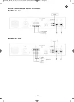
Page 5: ...CONNECTION EXAMPLES FOR 1 AND 2 ZONES 1 ZONE 2 ZONES 5 EN MA 91RUZ_MANUAL_ EN_ES_FR_PT _A5c_20200506 2020 qxp_Maquetaci n 1 6 5 20 11 38 P gina 5...

Page 6: ...mm jack 85 mV RMS and 80 mV RMS 1 100 V line spring terminals OUTPUTS 1 line out 2 x RCA 700 mV CONTROLS Tone Bass 10 dB Treble 10 dB Volume inputs 1 to 2 zones 1 to 2 aux mp3 general volume and USB...

Page 7: ...do radio permiten pasar al anterior siguiente punto de frecuencia con un paso de 0 1 MHz 3 VOL VOL controles de volumen del reproductor USB SD MP3 con sintonizador digital FM 4 Perto de conexi n de ta...

Page 8: ...reproductores de CD etc PHANTOM 24 V en esta posici n a las entradas pueden conectarse micr fonos de condensador electret que requieran alimentaci n phantom 24 V MIC en esta posici n a las entradas p...

Page 9: ...la alimentaci n Conecte los equipos de audio o micr fonos deseados a las entradas correspondientes Si conecta un micr fono din mico en la entrada 1 2 sit e el selector en la posici n MIC Si conecta un...

Page 10: ...EJEMPLO DE CONEXI N PARA 1 O 2 ZONAS Instalaci n de 1 zona Instalaci n de 2 zonas 10 ES MA 91RUZ_MANUAL_ EN_ES_FR_PT _A5c_20200506 2020 qxp_Maquetaci n 1 6 5 20 11 38 P gina 10...

Page 11: ...RCA y jack 3 5 mm 85 mV RMS y 80 mV RMS 1 l nea 100 V terminales a presi n SALIDAS 1 line out 2 x RCA 700 mV CONTROLES Tono Graves 10 dB Agudos 10 dB Volumen entradas 1 a 2 zonas 1 a 2 aux mp3 volumen...

Page 12: ...de radio permettent de passer le point de fr quence ant rieur suivant avec un pas de 0 1 MHz 3 VOL VOL contr les de volume du reproducteur USB SD MP3 avec syntoniseur num rique FM 4 Port de connexion...

Page 13: ...ANTOM 24 V peuvent se connecter aux entr es des microphones de condensateur lectret qui demandent une alimentation phantom 24 V MIC peuvent se connecter aux entr es des microphones de basse imp dance...

Page 14: ...appareils audio ou microphones souhait s aux entr es correspondantes Si vous connectez un microphone dynamique l entr e 1 ou 2 placez le s lecteur en position MIC Si vous connectez un microphone de c...

Page 15: ...EXEMPLE DE CONNEXION POUR 1 OU 2 ZONES Installation de 1 zone Installation de 2 zones 15 PT FR MA 91RUZ_MANUAL_ EN_ES_FR_PT _A5c_20200506 2020 qxp_Maquetaci n 1 6 5 20 11 38 P gina 15...

Page 16: ...iaire 2 x RCA y jack 3 5 mm 85 mV RMS et 80 mV RMS 1 ligne 100 V borniers pression SORTIES 1 line out 2 x RCA 700 mV CONTR LES Ton Graves 10 dB Aigus 10 dB Volume entr es 1 2 zones 1 2 aux MP3 volume...

Page 17: ...o ponto de frequ ncia anterior seguinte a um intervalo de 0 1 MHz 3 VOL VOL controlos de volume do leitor USB SD MP3 com sintonizador digital FM 4 Porta para ligar cart es SD 5 Porta para ligar dispo...

Page 18: ...in micos 5 Alimenta o CA 6 GND parafuso para tomada de terra para usar caso a tomada de corrente n o a tenha incorporada 7 Sa da para colunas Para ligar colunas em baixa imped ncia 4 e em alta imped n...

Page 19: ...o MIC Se ligar um microfone de condensador coloque o seletor na posi o PHANTOM 24 V Se ligar uma fonte de n vel de linha na entrada 1 ou 2 coloque o seletor na posi o LINE Se desejar pode ligar uma f...

Page 20: ...20 PT EXEMPLOS DE CONEX O PARA ZONAS 1 E 2 Instala o de 1 zona Instala o de 2 zona MA 91RUZ_MANUAL_ EN_ES_FR_PT _A5c_20200506 2020 qxp_Maquetaci n 1 6 5 20 11 38 P gina 20...

Page 21: ...ar 2 x RCA y jack 3 5 mm 85 mV RMS e 80 mV RMS 1 linha 100 V terminais a press o SA DAS 1 line out 2 x RCA 700 mV CONTROLOS Tom Graves 10 dB Agudos 10 dB Volume entradas 1 a 2 zonas 1 a 2 aux mp3 volu...

Page 22: ...22 MA 91RUZ_MANUAL_ EN_ES_FR_PT _A5c_20200506 2020 qxp_Maquetaci n 1 6 5 20 11 38 P gina 22...

Page 23: ...23 MA 91RUZ_MANUAL_ EN_ES_FR_PT _A5c_20200506 2020 qxp_Maquetaci n 1 6 5 20 11 38 P gina 23...

Page 24: ...www fonestar com MA 91RUZ_MANUAL_ EN_ES_FR_PT _A5c_20200506 2020 qxp_Maquetaci n 1 6 5 20 11 38 P gina 24...

Reviews: