EN
- 4 -
CONNETION
- Make the connections with the amplifier and all the audio system components switched off and
disconnected from the power supply.
- Firstly, connect the audio sources to the inputs. For example, connect a dynamic microphone to the
INPUT 1 input and select the MIC position in the input sensitivity selector. If you use a preamplified table
microphone, select the LINE position.
- Then, connect the speakers to the speaker output. Use the 4-8 Ω low impedance output or the 100, 75
or 25 V line output depending on the speakers that you are going to connect. Do not use both types of
output at the same time.
- If you use the low impedance output, you must connect the speakers in a series/parallel circuit so
that the speaker load impedance is the same as the amplifier impedance and the power supplied by
the amplifier does not exceed what is supported by the speakers.
- If you use the 100, 75 or 25 V high impedance line output, you must connect all the speakers in
parallel and the sum of the power of all the speakers must not exceed the power supplied by the
amplifier.
- Once the connections have been made, according to your needs, connect the system to the mains and
switch it on. After using it, do not forget to switch it off and disconnect it from the mains.
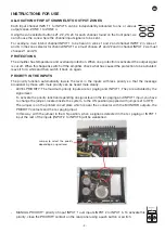
1 2 3 4
1 2 3 4
AUDIO PLAYER
PRIORITY
ZONE 1 (100 V LINE) - 120 W RMS
ZONE 2 (100 V LINE) - 120 W RMS
ZONE 3 (100 V LINE) - 120 W RMS
ZONE 4 (100 V LINE) - 120 W RMS
TELEPHONE
EXCHANGE
POWER AMPLIFIER
INPUT
ZONE 1 (100 V LINE)
100 V LINE
SPEAKER OUTPUT
To increase the power in a certain zone, connect the line output for the chosen zone to a power amp input.
Use the 100 V high impedance line output from the power amp to connect the speakers as shown in the
following diagram.
1 2 3 4
1 2 3 4
AUDIO PLAYER
PRIORITY
ZONE 1 (100 V LINE) - 120 W RMS
ZONE 2 (100 V LINE) - 120 W RMS
ZONE 3 (100 V LINE) - 120 W RMS
ZONE 4 (100 V LINE) - 120 W RMS
TELEPHONE
EXCHANGE
POWER AMPLIFIER
INPUT
ZONE 1 (100 V LINE)
100 V LINE
SPEAKER OUTPUT
Summary of Contents for MAZ-4480
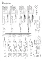
Page 6: ...EN 6 BLOCK DIAGRAM INPUT 1 INPUT 2 INPUT 3 INPUT 4 INPUT 5 Z2 Z3 Z4 Z1...
Page 12: ...EN 12 ES DIAGRAMA DE BLOQUES INPUT 1 INPUT 2 INPUT 3 INPUT 4 INPUT 5 Z2 Z3 Z4 Z1...
Page 24: ...24 DIAGRAMA DE BLOCOS INPUT 1 INPUT 2 INPUT 3 INPUT 4 INPUT 5 Z2 Z3 Z4 Z1...
Page 26: ......
Page 27: ......
Page 28: ...www fonestar com...

