EN
- 5 -
INSTRUCTIONS FOR USE
ALLOCATION OF INPUT CHANNELS TO OUTPUT ZONES
Each input channel INPUT 1 to INPUT 5 can be independently allocated to one or various
output zones, ZONE 1 to ZONE 4.
Using the zone selector buttons Z1, Z2, Z3, Z4 for each channel, found on the front panel, we
can choose the zone where the channel input signal is to be sent.
For example, if we intend channel INPUT 1 to be heard in zones 1 and 2 and channel INPUT 2 in zones 1
and 3, in the zone selector for channel INPUT 1 we must choose Z1 and Z2 and in channel INPUT 2 we must
choose Z1 and Z3.
PROTECTIONS
The amplifier has temperature and overload protection. When one protection is activated the output signal
is cut off. When this happens switch off the amplifier, check what has caused the protection to be activated,
leave it for a while and then switch it back on again.
PRIORITY IN THE INPUTS
The priority function automatically lowers the level in the inputs with less priority so that the message
broadcast by those with more priority can be heard more clearly.
- LEVEL PRIORITY: The maximum priority inputs are tel. paging and INPUT 1. They are activated by the
signal level.
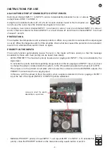
To activate the priority function depending on signal level in the tel. paging and INPUT 1 input, you have
to change the jumper, located inside the system, to the ON position (supplied with jumper set to OFF).
The jumper is on the printed circuit plate which is near the connector with the MONITOR outputs, the
PRIORITY contacts and the tel. paging input.
In this way, with the jumper in the ON position, when a signal is detected in the tel. paging or INPUT 1
input the rest of the inputs (INPUT 2 to INPUT 5) will be weakened.
Jumper to select the priority
depending on signal level
- MANUAL PRIORITY: priority of input INPUT 1 over inputs INPUT 2 to INPUT 5. To activate this
priority, close the PRIORITY contact on the rear panel using a push button or switch.
1 2 3 4
1
2
3
1 2
8
9
10
3
4
5
6
7
4
5
6
7
8
1 2 3 4
1
2
3
1 2
8
9
10
3
4
5
6
7
4
5
6
7
8
Summary of Contents for MAZ-4480
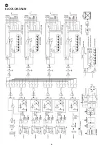
Page 6: ...EN 6 BLOCK DIAGRAM INPUT 1 INPUT 2 INPUT 3 INPUT 4 INPUT 5 Z2 Z3 Z4 Z1...
Page 12: ...EN 12 ES DIAGRAMA DE BLOQUES INPUT 1 INPUT 2 INPUT 3 INPUT 4 INPUT 5 Z2 Z3 Z4 Z1...
Page 24: ...24 DIAGRAMA DE BLOCOS INPUT 1 INPUT 2 INPUT 3 INPUT 4 INPUT 5 Z2 Z3 Z4 Z1...
Page 26: ......
Page 27: ......
Page 28: ...www fonestar com...

