background image

INSTRUCTION MANUAL/MANUAL DE USUARIO/

MODE D’EMPLOI/MANUAL DE INSTRUÇÕES

MXZ-2036

MULTIZONE MIXER/PREAMPLIFIER

MEZCLADOR/PREAMPLIFICADOR MULTIZONA

MÉLANGEUR/PRÉAMPLIFICATEUR MULTIZONE

MISTURADOR/PRÉ-AMPLIFICADOR MULTI-ZONA

Summary of Contents for MXZ-2036

Page 1: ...N MANUAL MANUAL DE USUARIO MODE D EMPLOI MANUAL DE INSTRU ES MXZ 2036 MULTIZONE MIXER PREAMPLIFIER MEZCLADOR PREAMPLIFICADOR MULTIZONA M LANGEUR PR AMPLIFICATEUR MULTIZONE MISTURADOR PR AMPLIFICADOR M...

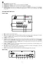
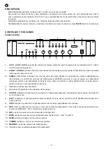
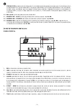
Page 2: ...X 3 the AUX 1 AUX 2 and AUX 3 inputs on the rear panel 2 ZONE 1 ZONE 6 output zone activation deactivation controls The lit LED indicator means that the zone is activated 3 SIGNAL LED output signal le...

Page 3: ...E REC message recording volume control 11 MESSAGE VOLUME PLAY message playback volume control 12 48 V phantom power supply switch This switch has two positions PHANTOM 48 V in this position the MIC in...

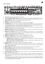
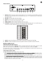
Page 4: ...2036 3 POWER LED power indicator 4 ALARM alarm push button If this is pressed down for 2 seconds playback is activated for the message stored in position 3 of the mixer MXZ 2036 memory and it is broad...

Page 5: ...ays The chimes can be played remotely through the microphone mod M 203 Select the zone or zones to which you wish to send the chimes using the buttons ZONE 1 to 6 Then press the TALK button which acti...

Page 6: ...e ampli er per zone or as a 100 V line switching unit with one ampli er for background music and another one for paging Once the connections have been made according to your needs connect the devices...

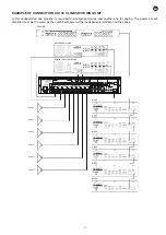
Page 7: ...ONE 1 ZONE 2 ZONE 3 ZONE 4 ZONE 5 ZONE 6 AUX 1 REC REPEAT PLAY MODE AUX 2 AUX 3 MIC GAIN MESSAGE GAIN VOLUME PRIORITY PLAY REC 3 2 1 OFF NORMAL ALARM VOLUME CHIME VOLUME REMOTE MIC ON OFF MIC PHANTOM...

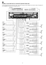
Page 8: ...EC REPEAT PLAY MODE AUX 2 AUX 3 MIC GAIN MESSAGE GAIN VOLUME PRIORITY PLAY REC 3 2 1 OFF NORMAL ALARM VOLUME CHIME VOLUME REMOTE MIC ON OFF MIC PHANTOM 48 V 24 V DC ZONE ATT PRIORITY OUT BGM PAGING OU...

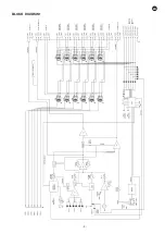
Page 9: ...EN 9 BLOCK DIAGRAM BGM OUT BGM PAGING OUT BGM IN PAGING IN PAGING OUT 24 V DC ZONE ATT PRIORITY OUT SIGNAL VU METER REPEAT ON REPEAT OFF BGM REMOTE MIC MIC MIC AUX 1 AUX 2 AUX 2...

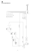
Page 10: ...EN 10 BLOCK DIAGRAM M 203...

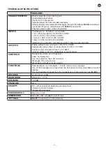
Page 11: ...V RMS Background music output screw terminals 47 000 1 5 V RMS 6 zones screw terminals 47 000 1 5 V RMS 6 priority relays in 24 V DC attenuators screw terminals CONTROLS Microphone volume aux and gen...

Page 12: ...s entradas AUX 1 AUX 2 o AUX 3 del panel posterior 2 ZONE 1 ZONE 6 controles de activaci n o desactivaci n de las zonas de salida El indicador luminoso encendido indica que la zona est activa 3 SIGNAL...

Page 13: ...zonas activas en modo ALARM el mensaje se emitir por todas las zonas a m ximo volumen aunque se encuentren desactivadas 10 MESSAGE VOLUME REC control de volumen de grabaci n de los mensajes 11 MESSAG...

Page 14: ...PHONE WITH ZONE SELECTOR MULTIZONE MICROPHONE M 203 CAUTION RISK OF ELECTRIC SHOCK DO NOT OPEN 10 10 1 2 3 1 1 2 3 4 5 6 7 8 2 3 4 7 6 5 1 MIC entrada de micr fono conector XLR 2 LINK indicador lumino...

Page 15: ...a para conectar el siguiente micr fono con selector de zonas mod M 203 INSTRUCCIONES DE USO CONEXI N DEL MICR FONO M 203 Para la conexi n del micr fono mod M 203 se utiliza un cable de control tipo Ca...

Page 16: ...fono mod M 203 El mensaje se emitir s lo en las las zonas seleccionadas si el mezclador est con gurado en modo NORMAL o en todas las zonas si el mezclador est con gurado en modo ALARM El mensaje se r...

Page 17: ...instalados en todas las zonas BGM PAGING ZONE 1 ZONE 2 ZONE 3 ZONE 4 ZONE 5 ZONE 6 AUX 1 REC REPEAT PLAY MODE AUX 2 AUX 3 MIC GAIN MESSAGE GAIN VOLUME PRIORITY PLAY REC 3 2 1 OFF NORMAL ALARM VOLUME...

Page 18: ...ona respectiva BGM PAGING ZONE 1 ZONE 2 ZONE 3 ZONE 4 ZONE 5 ZONE 6 AUX 1 REC REPEAT PLAY MODE AUX 2 AUX 3 MIC GAIN MESSAGE GAIN VOLUME PRIORITY PLAY REC 3 2 1 OFF NORMAL ALARM VOLUME CHIME VOLUME REM...

Page 19: ...EN 19 ES DIAGRAMA DE BLOQUES BGM OUT BGM PAGING OUT BGM IN PAGING IN PAGING OUT 24 V DC ZONE ATT PRIORITY OUT SIGNAL VU METER REPEAT ON REPEAT OFF BGM REMOTE MIC MIC MIC AUX 1 AUX 2 AUX 2...

Page 20: ...EN 20 ES DIAGRAMA DE BLOQUES M 203...

Page 21: ...sica ambiente terminales roscados 47 000 1 5 V RMS 6 zonas terminales roscados 47 000 1 5 V RMS 6 rel s de prioridad en atenuadores 24 V CC terminales roscados CONTROLES Volumen de micr fono auxiliar...

Page 22: ...lecteur d entr e de musique ambiance qui permet de choisir entre les entr es AUX 1 AUX 2 et AUX 3 du panneau arri re 2 ZONE 1 ZONE 6 contr les d activation ou de d sactivation des zones de sortie L in...

Page 23: ...mode ALARM le message sera mis pour toutes les zones m me si elles sont d sactiv es 10 MESSAGE VOLUME REC contr le du volume de l enregistrement des messages 11 MESSAGE VOLUME REC contr le du volume d...

Page 24: ...M 203 MICROPHONE WITH ZONE SELECTOR MULTIZONE MICROPHONE M 203 CAUTION RISK OF ELECTRIC SHOCK DO NOT OPEN 10 10 1 2 3 1 1 2 3 4 5 6 7 8 2 3 4 7 6 5 1 MIC entr e de microphone connecteur XLR 2 LINK in...

Page 25: ...ON ON N de micro Config des interrupteurs 7 LINE IN connecteur d entr e de la ligne de donn es et audio du m langeur mod le MXZ 2036 8 LINK OUT connecteur de sortie de la ligne pour connecter le micr...

Page 26: ...tre sur le mode ALARM Pour reproduire le message 3 maintenir appuyez durant 2 segondes le bouton ALARM du microphone mod le M 203 Le message sera mis dans les zones s lectionn es si le m langeur est c...

Page 27: ...s BGM PAGING ZONE 1 ZONE 2 ZONE 3 ZONE 4 ZONE 5 ZONE 6 AUX 1 REC REPEAT PLAY MODE AUX 2 AUX 3 MIC GAIN MESSAGE GAIN VOLUME PRIORITY PLAY REC 3 2 1 OFF NORMAL ALARM VOLUME CHIME VOLUME REMOTE MIC ON OF...

Page 28: ...ODE AUX 2 AUX 3 MIC GAIN MESSAGE GAIN VOLUME PRIORITY PLAY REC 3 2 1 OFF NORMAL ALARM VOLUME CHIME VOLUME REMOTE MIC ON OFF MIC PHANTOM 48 V 24 V DC ZONE ATT PRIORITY OUT BGM PAGING OUT BGM OUT PAGING...

Page 29: ...FR 29 DIAGRAMME DE BLOCS BGM OUT BGM PAGING OUT BGM IN PAGING IN PAGING OUT 24 V DC ZONE ATT PRIORITY OUT SIGNAL VU METER REPEAT ON REPEAT OFF BGM REMOTE MIC MIC MIC AUX 1 AUX 2 AUX 2...

Page 30: ...FR 30 DIAGRAMME DE BLOCS M 203...

Page 31: ...rniers filet s 47 000 1 5 V 6 zones borniers filet s 47 000 1 5 V 6 relais de priorit en att nuateurs 24 V CC borniers filet s CONTR LES Volume du microphone auxiliaire et g n ral S lection de zones 1...

Page 32: ...sica ambiente permite escolher de entre as entradas AUX 1 AUX 2 e AUX 3 do painel posterior 2 ZONE 1 ZONE 6 controlos para ativar ou desativar as zonas de sa da O indicador luminoso ligado indica que...

Page 33: ...er emitida unicamente pelas zonas ativas em modo ALARM a mensagem ser emitida por todas as zonas no volume m ximo mesmo que estejam desativadas 10 MESSAGE VOLUME REC controlo de volume de grava o das...

Page 34: ...SELECTOR MULTIZONE MICROPHONE M 203 CAUTION RISK OF ELECTRIC SHOCK DO NOT OPEN 10 10 1 2 3 1 1 2 3 4 5 6 7 8 2 3 4 7 6 5 1 MIC entrada de microfone conetor XLR 2 LINK indicador luminoso de liga o Este...

Page 35: ...OLUME controlo que regula o volume de sa da 3 TREBLE refor a ou atenua as frequ ncias agudas 10 dB 4 BASS refor a ou atenua as frequ ncias graves 10 dB 5 CHIME VOLUME controlo de volume dos tons music...

Page 36: ...damente 2 segundos o bot o ALARM do microfone M 203 Esta entrada tem prioridade sobre as restantes entradas MIC as mensagens 1 ou 2 e a entrada auxiliar AUX 1 AUX 2 ou AUX 3 a qual permanecer atenuada...

Page 37: ...nge 6 Orange Blanc 7 Vert 8 Vert Blanc 1 Azul 2 Azul Branco 3 Castanho 4 Castanho Branco 5 Laranja 6 Laranja Branco 7 Verde 8 Verde Branco 1 8 1 8 1 8 1 8 NOTA Os conetores devem ter a blindagem do ca...

Page 38: ...NE 2 ZONE 3 ZONE 4 ZONE 5 ZONE 6 AUX 1 REC REPEAT PLAY MODE AUX 2 AUX 3 MIC GAIN MESSAGE GAIN VOLUME PRIORITY PLAY REC 3 2 1 OFF NORMAL ALARM VOLUME CHIME VOLUME REMOTE MIC ON OFF MIC PHANTOM 48 V 24...

Page 39: ...MODE AUX 2 AUX 3 MIC GAIN MESSAGE GAIN VOLUME PRIORITY PLAY REC 3 2 1 OFF NORMAL ALARM VOLUME CHIME VOLUME REMOTE MIC ON OFF MIC PHANTOM 48 V 24 V DC ZONE ATT PRIORITY OUT BGM PAGING OUT BGM OUT PAGIN...

Page 40: ...PT 40 DIAGRAMA DE BLOCOS BGM OUT BGM PAGING OUT BGM IN PAGING IN PAGING OUT 24 V DC ZONE ATT PRIORITY OUT SIGNAL VU METER REPEAT ON REPEAT OFF BGM REMOTE MIC MIC MIC AUX 1 AUX 2 AUX 2...

Page 41: ...PT 41 DIAGRAMA DE BLOCOS M 203...

Page 42: ...sica ambiente terminais de rosca 47 000 1 5 V RMS 6 zonas terminais de rosca 47 000 1 5 V RMS 6 rel s de prioridade em atenuadores 24 V CC terminais de rosca CONTROLOS Volume de microfone auxiliar e...

Page 43: ......

Page 44: ...www fonestar com...

Reviews: