109
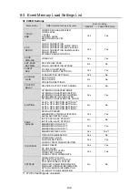
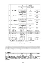
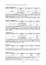
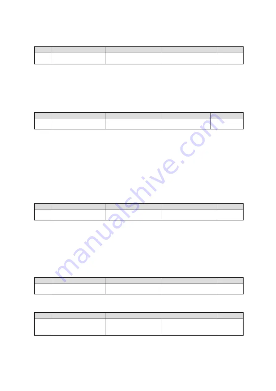
Setting 4 allows you to select a unit from which to load the memory data.
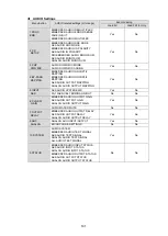
Memory Save
No.
Setting1
Setting2
Setting3
Setting4
24
Memory Save
Event
Salvo
Menu
No1 - 100
FA-10RU
MU
Selecting
Memory Save
under Setting 1 allows you to save the memory data to the memory
specified under Setting 2, 3 and 4, when the circuit is closed. See section 6-21.
“SALVO SAVE”,
“SAVE EVENT MEMORY” for details.
Setting 2 allows you to select a memory type.
Setting 3 allows you to select a memory number. (To change the Menu display, select
Menu.)
Setting 4 allows you to select a unit to which to save the memory data.
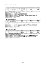
Menu Move
No.
Setting1
Setting2
Setting3
Setting4
25
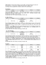
Menu Move
P000 - P1499
None
FS1 - FS10
None
Line1 - Line8
Selecting
Menu Move
under Setting 1 allows you to display the menu selected under Setting 2, 3,
and 4 when the circuit is closed.
Setting 2 allows you to select a menu number.
Setting 3 allows you to change an FS.
Setting 4 allows you to select the menu display row in which to set a setting. Lines are numbered 1
to 8 from top to bottom.
* If a menu number that does not exist is selected under Setting 2, the menu display will not be
changed. If the selected menu does not contain any FS or line selections, those settings will be
ignored. If an FA-1010 menu number is specified during FA-505 operation, the remote unit
automatically replaces it with the corresponding FA-505 menu.
Do
not
select FS6 to FS10 when connecting to FA-505 units.
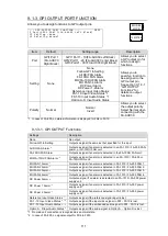
Color Correction Split
No.
Setting1
Setting2
Setting3
Setting4
26
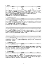
Color Correction Split
Off,Mode1, Mode2, Mode3
None
FS1 - FS10
None
Menu
Selecting
Color Correction Split
under Setting 1 allows you to display the menu selected under
Setting 2, 3, and 4 when the circuit is closed.
Setting 2 allows you to specify the Color Correction Split mode.
Setting 3 allows you to change an FS.
Setting 4 allows you to change the menu.
If an FA-1010 menu number is specified during FA-505 operation, the remote unit automatically
replaces it with the corresponding FA-505 menu.
Do
not
select FS6 to FS10 when connecting to FA-505 units.
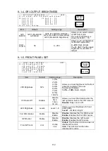
DRC Operate
No.
Setting1
Setting2
Setting3
Setting4
27
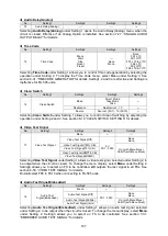
DRC Operate
On, Off, On/Off
None
FS1-FS2
None
Menu
Enabled for FA-9600 units but disabled for FA-1010/505 units.
Input Color Space
No.
Setting1
Setting2
Setting3
Setting4
28
Input Color Space
Rec. ITUR BT.709
Rec. ITUR BT.2020
User1-5
None
FS1-FS5
None
Menu
Selecting
Input Color Space
under Setting 1 allows you to display the menu selected under
Setting 2, 3, and 4 when the circuit is closed.
Setting 2 allows you to specify the Input Color Space mode.
Setting 3 allows you to select an FS. Setting to
None
selects the currently controlled FS.
Setting 4 allows you to change the menu.

