125
11-1-4. Setting GPI Functions
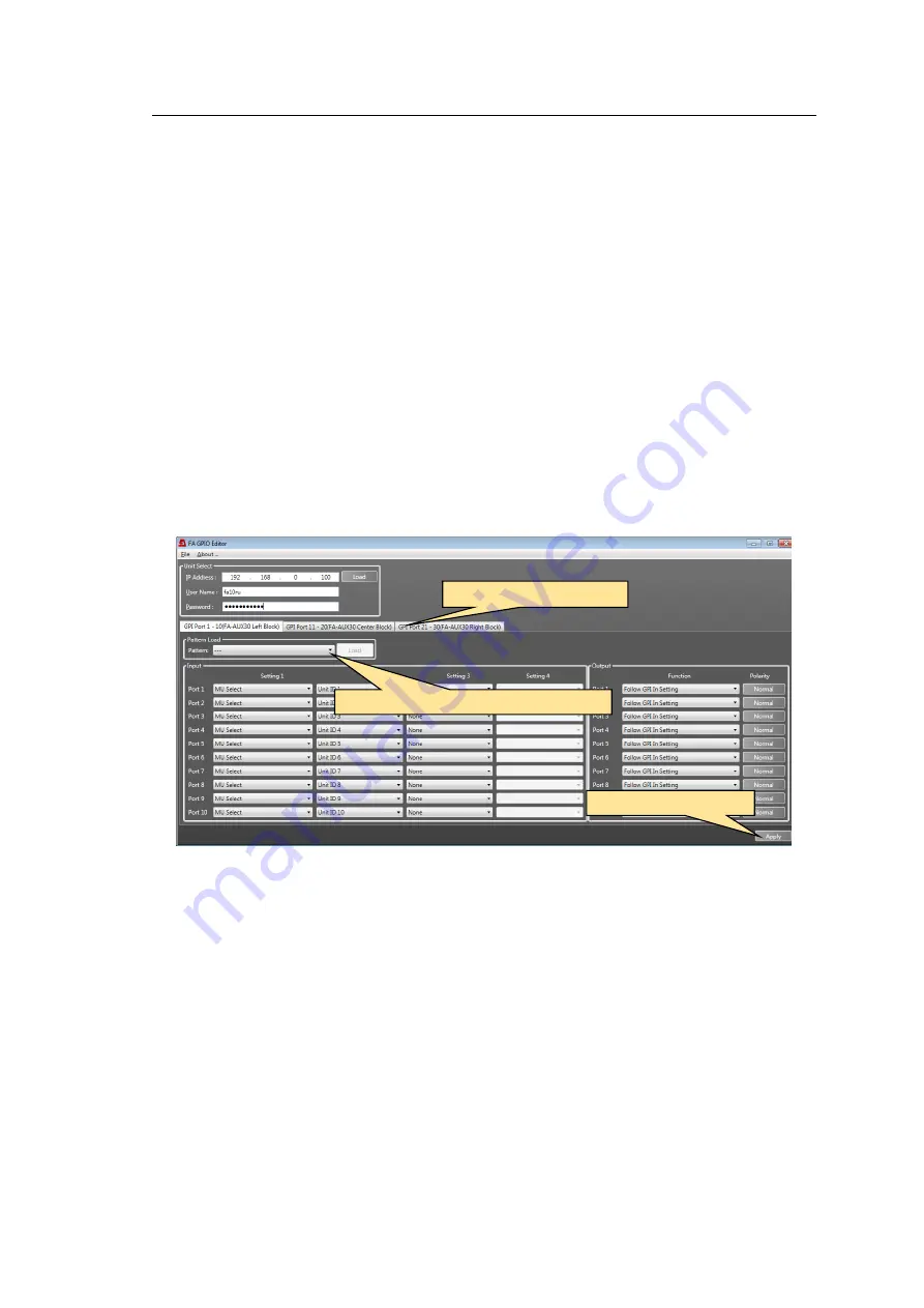
Use the FA-GPIO Editor to assign functions to 30 inputs and 30 outputs in GPI1, GPI2 and
GPI3 connectors. As factory default, GPI functions are all set to
None (no function).
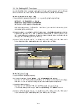
If Using Pattern Load (input only)
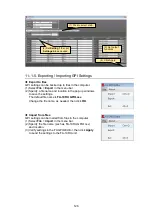
(1) Select a GPI connector (10 ports) by clicking a tab from the following three:
GPI Port 1
– 10 (FA-AUX30 Left Block)
GPI Port 11
– 20 (FA-AUX30 Center Block)
GPI Port 21
– 30 (FA-AUX30 Right Block)
Note that
“(FA-AUX30…)” indicates a button block (seen from the front side) when
connecting an FA-AUX30 unit.
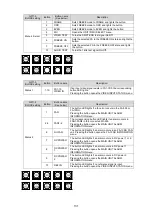
(2) Select a pattern (a combination of GPI input settings) in the
Pattern Load
, then click the
Load
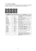
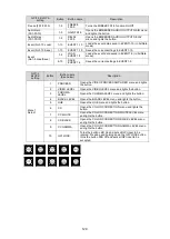
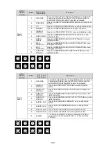
button. (See Sec.11-2. "GPI Input Patterns" for details on function patterns.) Ten
GPI inputs/outputs are quickly set. Loaded settings (including output functions) can be
changed. (See "If Setting Individually" below.)
(3) After all GPI settings are finished, click
Apply
to send the settings to the FA-10RU unit. If
a “Successful settings” message appears, GPI settings are complete.
If Setting Individually
(1) Select a GPI connector (10 ports).
(2) For input functions, first, set
Setting 1
then set
Settings 2-4
as needed.
See Sec. 9-1-2-1. "Setting Details via Setting 1-4" for details on individual input settings.
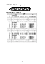
See Sec. 11-3. "GPI1-GPI3 Pin Assignments" for details on pin arrangements.
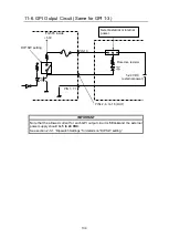
(3) Set GPI output functions.
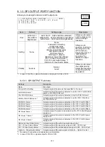
See Sec. 9-1-3-1. "GPI OUTPUT Functions" for details on output settings.
To invert the polarity of GPI output pulse, change
Polarity
from
Normal
to Invert.
(4) After all GPI settings are finished, click
Apply
to send the settings to the FA-10RU unit. If
a “Successful settings” message appears, GPI settings are complete.
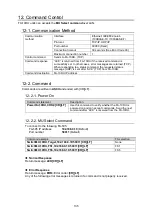
(1) Click to select a tab.
(2) Select a pattern, then click Load.
(3) Click Apply.

