15
5
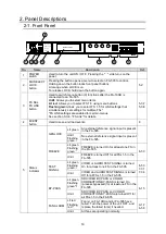
Status
indicator
DC POWER
Lit red
Flashing
red
*1
A power failure has occurred.
Power Off the unit and consult your FOR-A
reseller.
Unlit
Power supply is normal.
*1 The combination of Unlit/Flashing or Lit/Flashing is selectable. Refer to section
“9-1-6. STATUS LED MODE
SETTINGS” for details. The default setting is Lit.
No.
Name
Description
Ref.
6
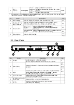
Menu display
Used to display menus and make operational settings.
7
Controls (F1-F4)
UNITY buttons
Used to change operational settings. Turn and select values.
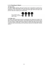
The Unity buttons return the settings to the default values.
8
Arrow buttons
Single-arrow
button
Used to move between parameters.
(Indicators light up to indicate the accessible
direction.)
Double-arrow
button
Used to move between menus. (Indicators light up
to indicate the accessible direction.))
9
Menu buttons
Used to select menus.
2-2. Rear Panel
No.
Name
Description
Ref.
1
TO MU
A LAN connector for FA-505 control.
Set the unique IP address and connect to the network.
2
GPI 1-GPI 3
Used to connect an FA-AUX30 or external expansion switch
panel(s).
3
FAN
Used to air-cool the unit to prevent overheating. Do not block
the ventilation with other equipment or objects. The FAN
ALARM on the front panel lights up if the fan fails.
4
Ground Terminal
Used to ground the unit to protect operators against static
electricity and electrical shock.
5
AC cord retaining clip
anchor hole
Used to anchor the AC cord retaining clip.
6
AC IN
Used to connect the unit to an AC power source.
(AC100V-240V 50/60Hz)
AC100-240V 50/60Hz IN
GPI3
GPI2
GPI1
TO MU
(10/100/1000BASE-T)

