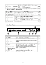
16
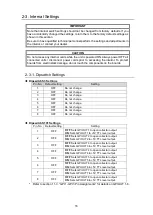
2-3. Internal Settings
IMPORTANT
Note that internal switch settings should not be changed from factory defaults. If you
have accidentally changed the settings, return them to the factory default settings as
shown in this section.
Be sure to have qualified technical personnel perform the settings and adjustments in
the interior, or contact your dealer.
CAUTION
Do not access any internal cards while the unit is powered ON. Always power OFF all
connected units / disconnect power cords prior to accessing the interior. To protect
boards from electrostatic damage, do not touch the components on the boards.
2-3-1. Dipswitch Settings
Dipswitch S3 Settings
Pin No.
Default setting
Setting
1
OFF
Do not change.
2
OFF
Do not change.
3
OFF
Do not change.
4
OFF
Do not change.
5
OFF
Do not change.
6
OFF
Do not change.
7
OFF
Do not change.
8
OFF
Do not change.
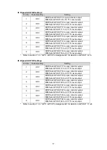
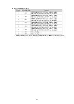
Dipswitch S101 Settings
Pin No.
Default setting
Setting
1
OFF
OFF
: Sets GPI OUT1 to open collector output.
ON
: Sets GPI OUT1 to +5V TTL level output.
2
OFF
OFF
: Sets GPI OUT2 to open collector output.
ON
: Sets GPI OUT2 to +5V TTL level output.
3
OFF
OFF
: Sets GPI OUT3 to open collector output.
ON
: Sets GPI OUT3 to +5V TTL level output.
4
OFF
OFF
: Sets GPI OUT4 to open collector output.
ON
: Sets GPI OUT4 to +5V TTL level output.
5
OFF
OFF
: Sets GPI OUT5 to open collector output.
ON
: Sets GPI OUT5 to +5V TTL level output.
6
OFF
OFF
: Sets GPI OUT6 to open collector output.
ON
: Sets GPI OUT6 to +5V TTL level output.
7
OFF
OFF
: Sets GPI OUT7 to open collector output.
ON
: Sets GPI OUT7 to +5V TTL level output.
8
OFF
OFF
: Sets GPI OUT8 to open collector output.
ON
: Sets GPI OUT8 to +5V TTL level output.
* Refer to section 11-3.
“GPI 1-GP I3 Pin Assignments” for details on GPI OUT 1-8.

