68
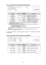
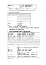
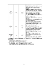
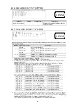
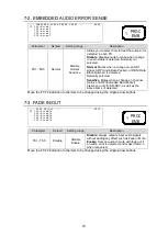
6-47. VIDEO INPUT LOSS MODE
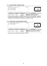
- - - V I D E O I N P U T L O S S M O D E - - -
P 5 7 8
F 1 F S 1 : B l a c k
F S 2 : B l a c k
F S 3 : B l a c k
F S 4 : B l a c k
F S 5 : B l a c k
Parameter
Default
Setting range
Description
FS1 - FS5
Black
Black
Blue
Red
Magenta
Green
Cyan
Yellow
Color Bar
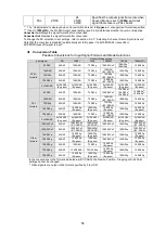
Auto Freeze
Out Disable
Allows you to select an operation for the
time the video signal input disappears for
each FS.
Black
– Yellow:
Outputs the selected back
color.
Color Bar:
Outputs the SMPTE color bar.
Auto Freeze:
Continues to output the
image from one frame before the input
signal loss.
Out Disable:
No signal output. (Sets the
output video signal to high impedance.)
To change the FS selection to set settings, refer to section 5-3-7.
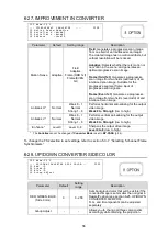
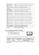
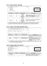
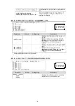
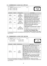
6-48. FS MODE SETTINGS
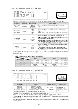
F S 2 N a m e : F S 2
- - - F S M O D E S E T T I N G S - - - P 5 7 9
F 1 S y n c M o d e : F r a m e
F r a m e D e l a y : O f f
3 G O u t P a y l o a d I D : O v e r w r i t e
4 K F S ( F S 2 - 5 ) : E n a b l e
4 k I n p u t M o d e : A u t o
2 S I O u t P a y l o a d I D : 2 S I
Parameter
Default
Setting range
Description
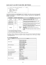
Sync Mode
Frame
Frame
Line
AVDL
Line(Minimum)
Frame
: Adjusts horizontal and vertical
timings of signals based on the adjusted
FA-505 system phases. Effective on both
synchronous and asynchronous signals.
Line/AVDL/Line(Minimum)
: Adjusts
horizontal and vertical timings of signals
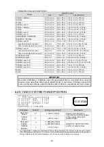
listed in the “Adjustable range per signal
format” table on page 70, based on the
adjusted FA-505 system phases.
Frame Delay
Off
Off
1 to 8 Frames
Allows you to set the amount of Frame Delay
for each FS.
Displays Unadjustable if Sync Mode is not
set to Frame.
3G Out
Payload ID
*1, *4
Overwrite
Overwrite
Pass
Allows you to select which Payload ID is
inserted into G SDI output. (See Sec.6-57.
Payload ID Input Status.)
Overwrite
: Inserts a new Payload ID that
matches to the output signal of 3G Level-A,
1080/59p(50p) Level-B or 2x1080/59i(50i)
Level B, according to input signal and
settings.
Pass
: Inserts the Payload ID of input signal.
10
SYSTEM
10
SYSTEM

