74
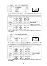
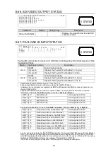
6-56. SDI VIDEO OUTPUT STATUS
- - - S D I V I D E O O U T P U T S T A T U S - - -
P 5 9 3
S D I 1 a / 1 b : 5 2 5 / 6 0
S D I 2 a / 2 b : 1 0 8 0 / 2 3 P s F
S D I 3 a / 3 b : 1 0 8 0 / 5 9 p L e v e l A
S D I 4 a / 4 b : 1 0 8 0 / 5 9 i
S D I 5 a / 5 b : 1 0 8 0 / 5 9 i
Parameter
Default
Setting range
Description
SDI1a/1b-SDI5a/5b
-
-
Displays the output format for each SDI
output connector.
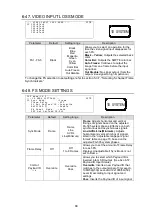
6-57. PAYLOAD ID INPUT STATUS
F S 1 N a m e : F S 1
- - - P A Y L O A D I D I N P U T S T A T U S - - - P 5 9 6
B y t e : 1 / 2 / 3 / 4 | C h e c k S u m
L i n k A : - - - / - - - / - - - / - - - | - - -
L i n k B : - - - / - - - / - - - / - - - | - - -
Payload ID and checksum values are 10-bit data (including parity bit) and displayed as three
hexadecimal digits.
Display
Input signal format
Description
Link A
SD/HD
No information display
3G Level A
Displays the Payload ID embedded in Y signal.
3G Level B
Displays the Payload ID embedded in Link A.
Link B
SD/HD
No information display
3G Level A
Displays the Payload ID embedded in C signal.
3G Level B
Displays the Payload ID embedded in Link B.
* Unavailable if FA-505 software version is less than 1.01.
* Payload Identification Codes for 2SI are compliant to SMPTE ST425-5.
* In
Auto
mode, input signals are regarded as
2SI
if a 2SI payload identification code is present in any
channel (FS2 to FS5).
* Payload Identification Codes for 2SI are located in Byte 4 in the payload ID information. Payload
Identification Codes for
3G-SDI Level-A
are located in
Bit [7..6]
of
Byte 4
.
Bit[7..6]
=
0
3G-SDI Link1
Corresponds to FS2.
Bit[7..6]
=
1
3G-SDI Link2
Corresponds to FS3.
Bit[7..6]
=
2
3G-SDI Link3
Corresponds to FS4.
Bit[7..6]
=
3
3G-SDI Link4
Corresponds to FS5.
Payload Identification Code for
3G-SDI Level-B
is located in
Bit [7..5]
of
Byte 4
.
Bit[7..5]
=
0
Data stream one on 3G-SDI Link1
Corresponds to FS2.
Bit[7..5]
=
1
Data stream two on 3G-SDI Link1
Corresponds to FS2.
Bit[7..5]
=
2
Data stream three on 3G-SDI Link2
Corresponds to FS3.
Bit[7..5]
=
3
Data stream four on 3G-SDI Link2
Corresponds to FS3.
Bit[7..5]
=
4
Data stream five on 3G-SDI Link3
Corresponds to FS4.
Bit[7..5]
=
5
Data stream six on 3G-SDI Link3
Corresponds to FS4.
Bit[7..5]
=
6
Data stream seven on 3G-SDI Link4
Corresponds to FS5.
Bit[7..5]
=
7
Data stream eight on 3G-SDI Link4
Corresponds to FS5.
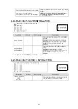
* An error will be indicated by the 0 STATUS flashing if an FS channel (FS2-FS5) has no 2SI identification
code, or 2SI channel correspondence is mismatched between Payload ID and FS channel information
when
2SI
is selected for 4k Input Mode. For example, when an error occurred on FS2 and FS3, pressing
the flashing 0 STATUS will
display the message, “Detected Error: FS2 FS3.”
If FS errors occur during menu operation, the following error messages will appear.
STATUS
0
STATUS
0


