80
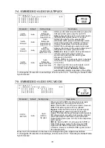
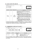
7-6. AES AUDIO SRC MODE
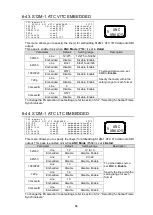
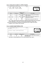
A E S ( A )
- - - A E S A U D I O S R C M O D E - - -
P 6 1 7
F 1 C H 1 / 2 : A u t o
F 2 C H 3 / 4 : A u t o
F 3 C H 5 / 6 : A u t o
F 4 C H 7 / 8 : A u t o
Parameter
Default Setting range
Description
CH1/2 -
CH7/8
Auto
Auto
SRC In
By-pass
Allows you to set the SRC circuit to pass or by-pass
audio signals per channel pair for the AES card
installed in slot A - D.
Auto:
Sets the SRC circuit to pass signals. However,
NON-PCM audio signals will be by-passed.
By-pass:
Sets the SRC circuit to by-pass signals. Set
to
By-pass
to output asynchronous audio signals.
To embed the asynchronous audio signals to SDI
video signals, an audio clock must be selected under
SDI Output Clock Select in the SDI Audio Output
Setting menu (sec. 9-3-10) for the respective audio
groups.
SRC In:
Sets the SRC circuit to pass both PCM or
NON-PCM signals. Useful for the irregular PCM
signal with the NON-PCM audio channel status
indication. However, real NON-PCM signals cannot
be output properly.
To change the slot selection to set settings, select a slot from A to D (AES(A) to AES(D)) in
the same procedure described in section 5-3-7.
“Selecting 5-channel Frame Synchronizers.”
* Displayed if an FA-10AES-BL/ FA-10AES-UBL is installed in slot A-D.
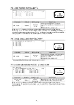
7-7. EMBEDDED AUDIO IN POLARITY
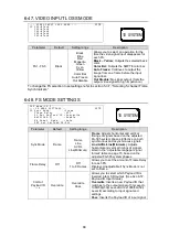
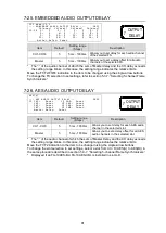
F S 1 N a m e : F S 1
- - - E M B E D D E D A U D I O P O L A R I T Y - - -
P 6 1 8
C H C H
C H C H
F 1 - F 4 1 : N O R M 2 : N O R M 3 : N O R M 4 : N O R M
5 : N O R M 6 : N O R M 7 : N O R M 8 : N O R M
9 : N O R M 1 0 : N O R M 1 1 : N O R M 1 2 : N O R M
1 3 : N O R M 1 4 : N O R M 1 5 : N O R M 1 6 : N O R M
Parameter
Default
Setting range
Description
CH1 - CH16
NORM
NORM
(Normal)
INV
(Invert)
Allows you to set polarity per audio
channel for each FS.
INV (Invert):
Reverses polarity.
Move the F1/F2/F3/F4 indication to the item to be changed using the single-arrow buttons.
To change the FS selection to set settings, refer to section 5-3-7.
CC
SETUP
2
CC
SETUP
2

