127
11-2. GPI Input Patterns
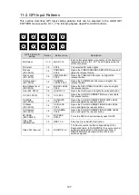
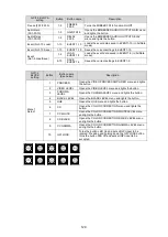
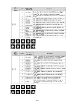
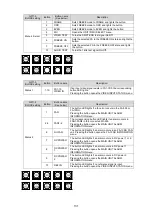
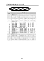
This section describes GPI Input setting patterns that can be selected in the LOAD GPI
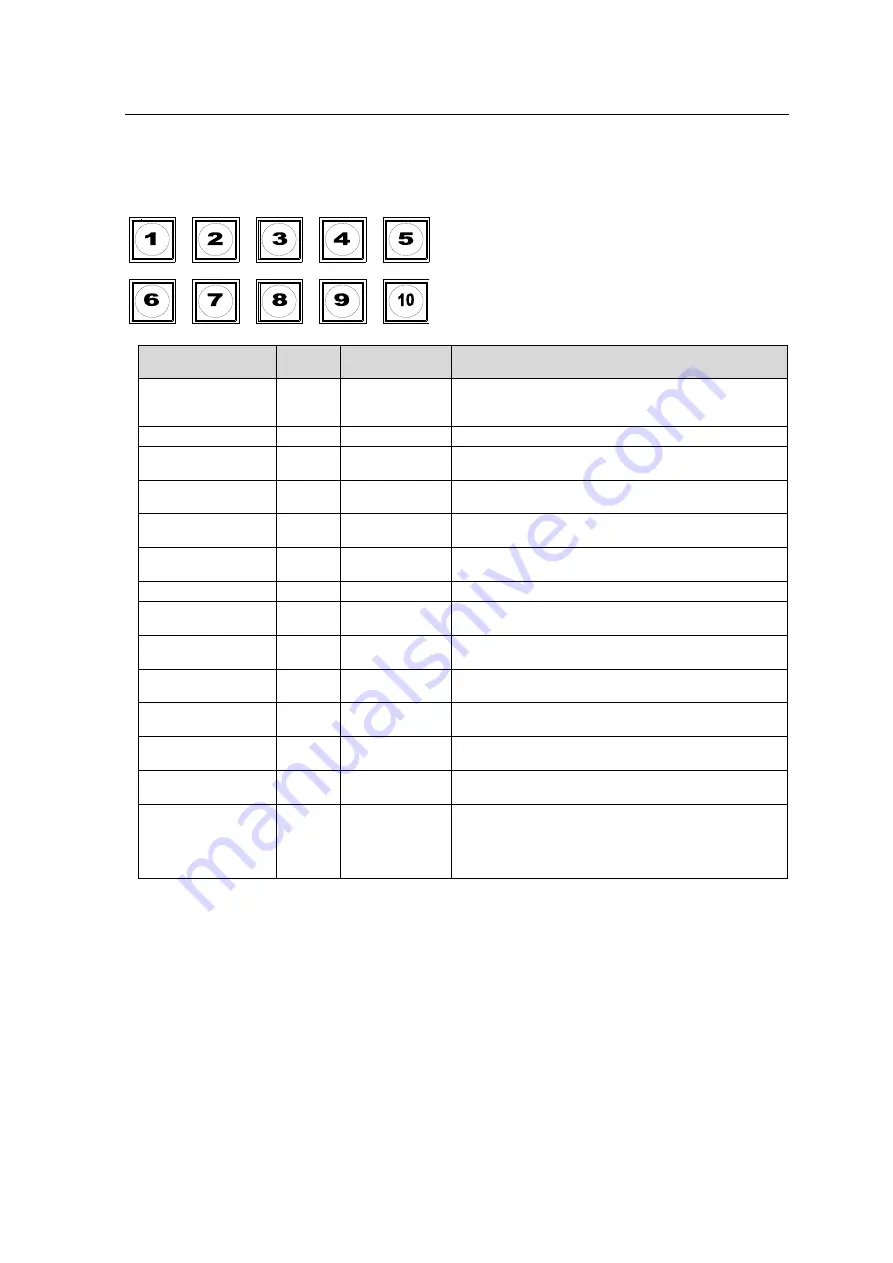
PATTERN menu (section 9-1-1). The following figures depict FA-AUX30 buttons.
GPI1-3 BLOCK
setting
Button
Button name
Description
MU Select
1-10
MU ID1-10
Each button establishes a connection to the Main Unit
registered with the ID 1-10. The LED lights while the
unit is connected.
FS Select
1-5
FS1-5
The selected FS button lights.
Process
(FS1-FS10)
1-5
PROCESS
FS1-5
Opens the VIDEO PROCESS AMPLIFIER menu and
lights the relevant button.
Video Level
(FS1-FS10)
1-5
VIDEO LEVEL
FS1-5
Opens the VIDEO LEVEL menu, and lights the
relevant button.
Chroma Level
(FS1-FS10)
1-5
CHROMA
LEVEL FS1-5
Opens the CHROMA LEVEL menu and lights the
relevant button.
Setup/Black Level
(FS1-FS10)
1-5
BLACK LEVEL
FS1-5
Opens the SETUP/BLACK LEVEL menu and lights
the relevant button.
Hue (FS1-FS10)
1-5
HUE FS1-5
Opens the HUE menu and lights the relevant button.
CC (FS1-FS10)
1-5
CC FS1-5
Opens the COLOR CORRECTION menu and lights
the relevant button.
CC White
(FS1-FS10)
1-5
CC WHITE
FS1-5
Opens the COLOR CORRECTION WHITE LEVEL
menu and lights the relevant button.
CC Black
(FS1-FS10)
1-5
CC BLACK
FS1-5
Opens the COLOR CORRECTION BLACK LEVEL
menu and lights the relevant button.
CC Gamma
(FS1-FS10)
1-5
CC GAMMA
FS1-5
Opens the COLOR CORRECTION GAMMA LEVEL
menu and lights the relevant button.
BY-PASS
(SDI1-SDI10)
1-5
BY-PASS
SDI1-5
Turns the SDI1-5 channel video bypass On/Off.
Clean SW
(Destination)
1-5
DEST 1-5
Selects a Clean Switch Destination.
Clean SW (Source)
1-5
SOURCE 1-5
The Source number button corresponding to the
Destination lights. In TAKE MODE, the source number
buttons to be selected by the switchover blink. In
DIRECT MODE, selecting a button that is unlit
switches signals.

