background image

HVS-GPIO128 

Interface Extension Unit 

1

st

 Edition

OPERATION 

MANUAL 

Summary of Contents for HVS-GPIO128

Page 1: ...HVS GPIO128 Interface Extension Unit 1st Edition OPERATION MANUAL ...

Page 2: ...ground the unit to gas lines units or fixtures of an explosive or dangerous nature Operation Hazard Do not operate the unit under hazardous or potentially explosive atmospheric conditions Doing so could result in fire explosion or other hazardous results Hazard Do not allow liquids metal pieces or other foreign materials to enter the unit Doing so could result in fire other hazards or a unit malfu...

Page 3: ...nd disconnect the power cord to avoid potentially hazardous conditions If problems similar to the above occur contact an authorized service representative before attempting to operate the unit again Rack Mount Brackets Ground Terminal and Rubber Feet Caution To rack mount or ground the unit or to install rubber feet do not use screws or materials other than those supplied Doing so may cause damage...

Page 4: ...G GPIO128 1 AC adapter 1 DC plug with lock system Power cord 1 EIA rack mount brackets 1 set Operation Manual 1 This manual Option ITEM QTY REMARKS AC adapter 1 For power redundancy Items needed to be prepared ITEM QTY REMARKS LAN cable 1 For HVS GPIO128 and switcher connection UTP Category 5e or 6 straight through Computer 1 For network settings for HVS GPIO128 LAN cable or RS 232C cable 1 For ne...

Page 5: ...GPI 1 4 8 2 3 2 SERIAL1 4 10 2 4 Internal Settings 11 3 Connecting to the HVS Switcher 12 4 Setup Menu 13 4 1 If Connecting via LAN 13 4 2 If Connecting via RS 232C 13 4 3 Changing HVS GPIO128 IP Address 14 4 4 Resetting the Setup Menu 15 5 Specifications and Dimensions 16 5 1 Unit Specifications 16 5 2 External Dimensions 16 ...

Page 6: ...escription A POWER Displays the power status B LAN Displays the connection status between HVS GPIO128 and switcher Also displays the Flash writing status C GPI Lights green when GPI signal is sent or received D SERIAL1 4 Lights green when serial data is sent or received E RESET Resets HVS GPIO128 Lit Indications for POWER and LAN indicators Indication Indicator Lit Green Flashing Red Lit Orange Un...

Page 7: ...on 1 RS 232C or RS 422 can be selected using switches on the card Default RS 232C See Sec 2 4 Internal Settings E GPI 1 Port 1 For GPI input output Function input and output free assignable 32 for each F GPI 2 Port 2 G GPI 3 Port 3 H GPI 4 Port 4 1 Serial interface extension may not be disabled depending on connection circumstances Refer to connection device manuals to select RS 232C or RS 422 A B...

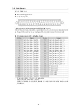
Page 8: ...5 24 GPI_IN TALLY_OUT 24 6 GPI_IN TALLY_OUT 06 25 GPI_IN TALLY_OUT 25 7 GPI_IN TALLY_OUT 07 26 GPI_IN TALLY_OUT 26 8 GPI_IN TALLY_OUT 08 27 GPI_IN TALLY_OUT 27 9 GPI_IN TALLY_OUT 09 28 GPI_IN TALLY_OUT 28 10 GPI_IN TALLY_OUT 10 29 GPI_IN TALLY_OUT 29 11 GPI_IN TALLY_OUT 11 30 GPI_IN TALLY_OUT 30 12 GPI_IN TALLY_OUT 12 31 GPI_IN TALLY_OUT 31 13 GPI_IN TALLY_OUT 13 32 GPI_IN TALLY_OUT 32 14 GPI_IN T...

Page 9: ...9 GPI IN circuit GPI OUT TALLY OUT circuit About 0 9 V when ON HVS GPIO128 VCC VCC Ext device Switch or Relay HVS GPIO128 VCC VCC Ext device Open Collector Ext device Max 40V HVS GPIO128 Max 100mA 10Ω ...

Page 10: ...ound 2 RxD Receive Data 2 T Transmit Data 3 TxD Transmit Data 3 R Receive Data 4 DTR Data Terminal Ready 4 SG Signal Ground 5 SG Signal Ground 5 NC N C 6 DSR Data Set Ready 6 SG Signal Ground 7 RTS Request To Send 7 T Transmit Data 8 CTS Clear To Send 8 R Receive Data 9 NC N C 9 FG Frame Ground Communication specifications Baud rate 19 200 38 400 57 600 115 200 bps Data 8 bit fixed Parity Odd Even...

Page 11: ... S4 4 Reset all HVS GPIO128 settings to default Switch ON Power ON Power OFF Switch OFF See Sec 4 4 Resetting the Setup Menu S12 S19 Switches Select RS 232C or RS 422 for each serial port using a switch pair S12 S14 SERIAL1 setting Switch settings RS 232C Default S13 S15 SERIAL2 setting S16 S18 SERIAL3 setting RS 422 S17 S19 SERIAL4 setting Other Switches Do not change settings S2 S3 For maintenan...

Page 12: ... switcher 3 Connect HVS GPIO128 to serial control devices Use the HVS switcher menu to set up the devices 4 Connect HVS GPIO128 to GPI controllers Use the HVS switcher menu to set up the devices 5 Use the supplied AC adapters to supply power to HVS GPIO128 LAN GPI 1 GPI 2 GPI 3 GPI 4 2 DC12V IN 1 RATING LABEL SERIAL SERVICE 1 2 3 4 LAN switch HVS Series MU LAN 2 SUB HVS GPIO128 LAN 1 MAIN PC for H...

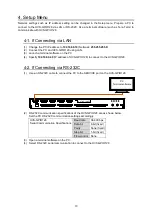
Page 13: ...f HVS GPIO128 to connect to the HVS GPIO128 4 2 If Connecting via RS 232C 1 Use an RS 232C cable to connect the PC to the SERVICE port on the HVS GPIO128 2 RS 232C communication specifications of the HVS GPIO128 are as shown below Set the PC RS 232C communication settings accordingly HVS GPIO128 Serial Communication Specifications Baud rate 38 400 bps Data bit 8 bit fixed Parity None fixed Stop bi...

Page 14: ...he Send HVS switcher s TCP port address Changing Network Settings 1 Enter in the terminal 2 Then enter setup case ignored and press Enter 3 The Setup menu content appears as shown below 4 At first to change the GPI Unit s IP address type 1 in the terminal then press Enter 1 5 Type a new IP address then press Enter IP 192 168 0 30 6 The screen returns to the Setup menu top Verify that the new IP ad...

Page 15: ...8 2 Unsecure two screws on both sides to remove the top plate 3 Turn on Dipswitch S4 4 See Sec 2 4 Internal Settings 4 Power on the HVS GPIO128 5 Check that POWER indicator on the front panel lights green 6 Power off the HVS GPIO128 7 Turn off Dipswitch S4 4 8 Return the top panel and secure two removed screws 9 HVS GPIO128 will be reset to factory default ...

Page 16: ... condensation Power 12V DC pin connector x 2 for power redundancy Power consumption 100V to 120V AC 8 VA 4 W 200V to 240V AC 13 VA 6 W Dimensions 430 W x 44 H x 110 D mm EIA1RU 480 W W rack mount brackets Weight 1 6 kg 5 2 External Dimensions All dimensions in mm LA N GPI 1 GPI 2 GPI 3 GPI 4 2 DC12V IN 1 RATING LABEL SERIA L SERVICE 1 2 3 4 POWER LAN SERIAL GPI 1 2 3 4 RESET HVS GPIO128 GPI UNIT 4...

Page 17: ...en the equipment is operated in a commercial environment This equipment generates uses and can radiate radio frequency energy and if not installed and used in accordance with the instruction manual may cause harmful interference to radio communications Operation of this equipment in a residential area is likely to cause harmful interference in which case the user will be required to correct the in...

Page 18: ...aly Tel 39 039 916 4811 Fax 39 039 878 140 FOR A UK Limited Trident Court 1 Oakcroft Road Chessington KT9 1BD U K Tel 44 0 20 3044 2935 Fax 44 0 20 3044 2936 FOR A Italia S r l Via Volturno 37 20861 Brugherio MB Italy Tel 39 039 881 086 103 Fax 39 039 878 140 FOR A Corporation of Korea 1007 57 5 Yangsan ro Yeongdeungpo gu Seoul 07271 Korea Tel 82 0 2 2637 0761 Fax 82 0 2 2637 0760 FOR A China Limi...

Reviews: