background image

3-2. How to Replace a Card (if only one card installed) 

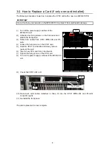
The following procedure shows how to replace the CPU1 card with a new one (MFR-61CPU). 
 

IMPORTANT 

Do not touch any components on the MFR-61CPU to protect it from electrostatic damage. 


(1)  Turn off the power supply switches of the  

MFR-6100 unit. 

(2)  Unfasten four fixing screws on the front panel and  

detach the front panel. 

(3)  Detach  the  cables  from  CPU1  MFR-LAN  and  PC-

LAN. 

(4)  Loosen the fixing screw on the CPU1 card. 
(5)  Grab the CPU1 card handle and slowly remove  

(pull out) the card. 

(6)  Insert a new CPU card firmly into the slot. 
(7)  Tighten the fixing screw on the CPU card. 
(8)  Turn on the power supply switches of the MFR-6100 

unit. 


(9)  Check that CPU1 LED is lit. 


(10) Re-connect  LAN  cables  detached  in  Step  (3)  into  the  CPU1  MFR-LAN  and  PC-LAN 

connection ports. 

(11)  Re-install the front panel. 
 
 
The card replacement is now complete. 


CPU1 card 

(4) 

(9) 

SLOT

INPUT

OUTPUT

INPUT

9 10 11 12 9 10 11 12 13 14 15 16 13 14 15 16

MFR-6100

A

C

1

0

0

-2

4

0

V

 5

0

/6

0

H

z

 IN

A

C

1

0

0

-2

4

0

V

 5

0

/6

0

H

z

 IN

1

2

INPUT

232C

422

SERIAL

REF IN

ALARM

CPU2

MFR-LAN

PC-LAN

FAN 6

CPU1

MFR-LAN

PC-LAN

FAN 5

INPUT

1

2

3

4

1

9

8

7

6

5

4

3

2

1

1

1

2

2

2

3

3

3

4

4

4

5

5

5

6

6

6

7

7

7

8

8

8

9

9

9

OUTPUT

1

2

3

4

5

6

7

8

1

1

1

1

1

1

1

1

2

2

2

2

2

2

2

2

3

3

3

3

3

3

3

3

4

4

4

4

4

4

4

4

5

5

5

5

5

5

5

5

6

6

6

6

6

6

6

6

7

7

7

7

7

7

7

7

8

8

8

8

8

8

8

8

9

9

9

9

9

9

9

9

INPUT

5

6

7

8

SLOT

INPUT

OUTPUT

INPUT

1 2 3 4 1

2 3

4 5

6

7 8 5

6 7 8

1

1

1

1

2

2

2

2

3

3

3

3

4

4

4

4

5

5

5

5

6

6

6

6

7

7

7

7

8

8

8

8

9

9

9

9

FAN 1

FAN 2

FAN 3

FAN 4

INPUT

OUTPUT

9

10

11

12

9

10

11

12

13

14

15

16

13

14

15

16

1

1

1

1

1

1

1

1

1

1

1

1

1

1

1

1

2

2

2

2

2

2

2

2

3

3

3

3

3

3

3

3

3

3

3

3

3

3

3

3

4

4

4

4

4

4

4

4

4

4

4

4

4

4

4

4

5

5

5

5

5

5

5

5

5

5

5

5

5

5

5

5

6

6

6

6

6

6

6

6

6

6

6

6

6

6

6

6

7

7

7

7

7

7

7

7

7

7

7

7

7

7

7

7

8

9

8

8

8

8

8

8

8

8

8

8

8

8

8

8

8

9

9

9

9

9

9

9

9

9

9

9

9

9

9

9

(1) 

Summary of Contents for MFR-41CPU

Page 1: ...MFR 41CPU MFR 61CPU Redundant CPU Card for MFR 4100 MFR 6100 1st Edition Rev 1 INSTALLATION GUIDE...

Page 2: ...ived items against the packing list below Check to ensure no damage has occurred during shipment If damage has occurred or items are missing inform your supplier immediately Packing List ITEM QTY REMA...

Page 3: ...ned for the MFR 4100 MFR 6100 A standard MFR 4100 MFR 6100 comes with a single CPU card installed into one of its two CPU slots The optional MFR 41CPU MFR 61CPU allows you to operate the MFR 4100 MFR...

Page 4: ...bs 6 If necessary configure the network settings for CPU2 and the settings for the number of CPU operating days See Main Unit Settings for network settings and Warning of CPU Consecutive Operating Day...

Page 5: ...fixing screw on the CPU card 8 Turn on the power supply switches of the MFR 4100 unit 9 Check that CPU1 LED is lit 10 Re connect LAN cables detached in Step 3 into the CPU1 MFR LAN and PC LAN connecti...

Page 6: ...he menu display open the SETTING SWAP ACTIVE CPU menu and turn CONTROL to select EXECUTE then press CONTROL Now Executing is displayed and the active CPU is switched from CPU2 to CPU1 See Swapping Act...

Page 7: ...e card installation is now complete MFR POWER 2 ON OFF POWER 1 ON OFF MFR 6100 ROUTING SWITCHER POWER CPU2 CPU1 MFR 61CPU installation slot 3 SLOT INPUT OUTPUT INPUT 9 10 11 12 9 10 11 12 13 14 15 16...

Page 8: ...el The card replacement is now complete CPU1 card 4 9 SLOT INPUT OUTPUT INPUT 9 10 11 12 9 10 11 12 13 14 15 16 13 14 15 16 MFR 6100 AC100 240V 50 60Hz IN AC100 240V 50 60Hz IN 1 2 INPUT 232C 422 SERI...

Page 9: ...for details 12 Check that CPU1 LED is lit 13 Re install the front panel The card replacement is now complete When replacing the CPU2 card Follow the same procedure as above except step 11 If necessar...

Page 10: ...rope S r l Via Volturno 37 20861 Brugherio MB Italy Tel 39 039 916 4811 Fax 39 039 878 140 FOR A UK Limited Trident Court 1 Oakcroft Road Chessington KT9 1BD U K Tel 44 0 20 3044 2935 Fax 44 0 20 3044...

Reviews: