8
2. Panel Descriptions
2-1. UFM-30MUX
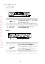
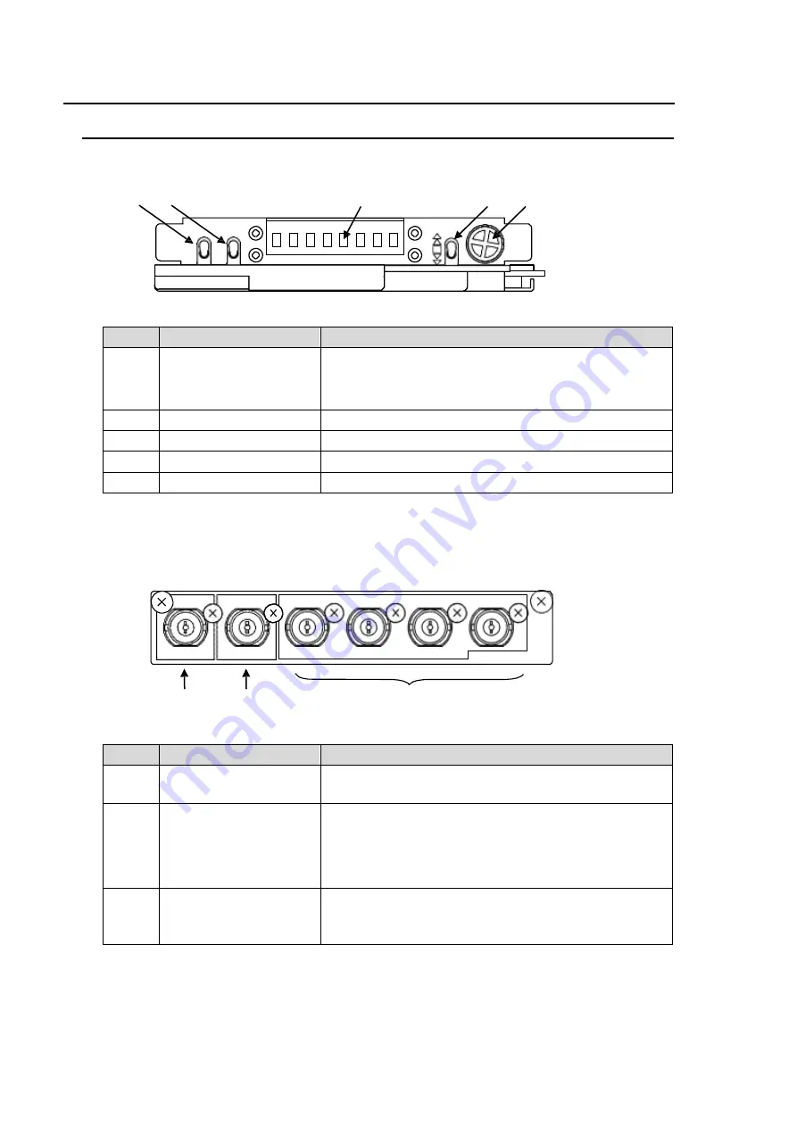
Front Panel
(1)
(2)
(3)
(4)
(5)
No.
Name
Description
(1)
OPERATE/LOCK
If set to OPERATE, the switch is set to Menu mode and
menu settings can be made.
If set to LOCK, the switch is set to Menu Lock mode and
menu settings cannot be made.
(2)
AES/LTC switch
Switches the 7/8-LTC port between AES 7/8 and LTC.
(3)
Display panel
Used to display menus and perform operational settings.
(4)
Up/Down switch
Used to move to higher or lower menu layers.
(5)
Menu Control
Used to perform menu settings.
Rear Panel
(1)
(2)
(3)
No.
Name
Description
(1)
3G/HD/SD-SDI
INPUT
Used to input serial digital component video.
(2)
3G/HD/SD-SDI
OUTPUT
Used to output serial digital component video, in which
specified audio channels are multiplexed (embedded).
The SDI input signal is directly sent to this output via
relay, if set to BYPASS or the power supply is down.
(See section 6-5-1. "SDI BYPASS."
(3)
DIGITAL AUDIO IN
Used to input 4 AES/EBU stereo pairs.
Channel 7/8 input can be changed to an LTC input.
(See (2) in Front Panel above.)
INPUT
OUTPUT
1/2
3/4
5/6
7/8-LTC
3G/HD/SD-SDI 3G/HD/SD-SDI
DIGITAL AUDIO IN
UFM-30MUX
PUSH
OPERATE
LOCK
AES
LTC
UFM-30MUX
USO
RESTRITO


