13
3-9. ALARM Connector
9-pin D-sub female
ALARM Connector Assignment Table (9-pin D-sub female)
No.
Signal
Signal Details
1
ALARM 1
ALARM 1 to 6 functions assigned through WebGUI setting page.
Refer to Sec. 9-2. "Alarm
Tab.”
2
ALARM 2
3
ALARM 3
4
ALARM 4
5
ALARM 5
6
ALARM 6
7
GND
GND
8
GND
GND
9
GND
GND
*
Open collector alarm output (ALARM 1 to 6)
Maximum current limit: 24VDC / 50mA
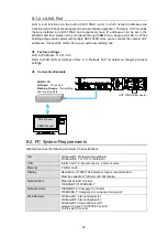
3-9-1. Example of Alarm Connection
Example of ALARM (Open-Collector Output) Circuit
Matching connector
9-pin D-sub male
*Using inch screws
Power
Supply
USF-105AS Side
Set the resistance so that the output pin
current stays within 50mA.
R
External power supply
Max. +24VDC.
GND
ALARM
50mA
Max


