21
8. Web Control
USF-105AS operation can be monitored by a web browser or SNMP Manager via a PC-network
connection. Power supply and fan states can be displayed by opening the USF-105AS WebGUI from a
web browser. Control and monitoring of the modules (*1) installed in USF-105AS can be done via
WebGUI. ALARM function assignments of the rear ALARM connector can be set via WebGUI. It is also
possible to monitor power supply, fan, temperature, modules (*1) through an SNMP manager.
(*1) Possible for the network support modules only. Refer to the operation manual of respective
modules.
8-1. Connecting USF-105AS to a PC
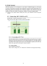
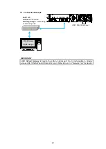
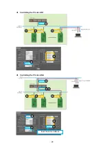
Connect LAN 1 or LAN A connector to a PC via a hub.
LAN 1 and LAN A have different functions. (See the figure below.)
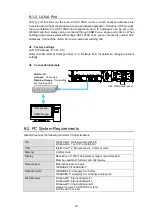
8-1-1. Connecting LAN 1 Port
Each slot network module is connected to the USF-105AS internal switching hub. The LAN 1
port on the rear panel are also connected to the internal switching hub. This requires different
IP addresses (other than 192.168.0.11 to 15 as factory default) to be set for other devices in
this network. When a large amount of data is to be exchanged per module, use the LAN 1 port.
(Refer to the respective module operation manual for details.)
Factory settings
LAN1 IP Address: 192.168.0.10
Refer to LAN 1 settings of Sec. 9-3
. "Network Tab” for details on changing network settings.


