8
3. Part Descriptions
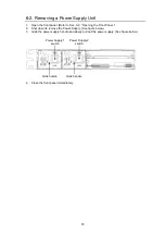
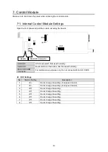
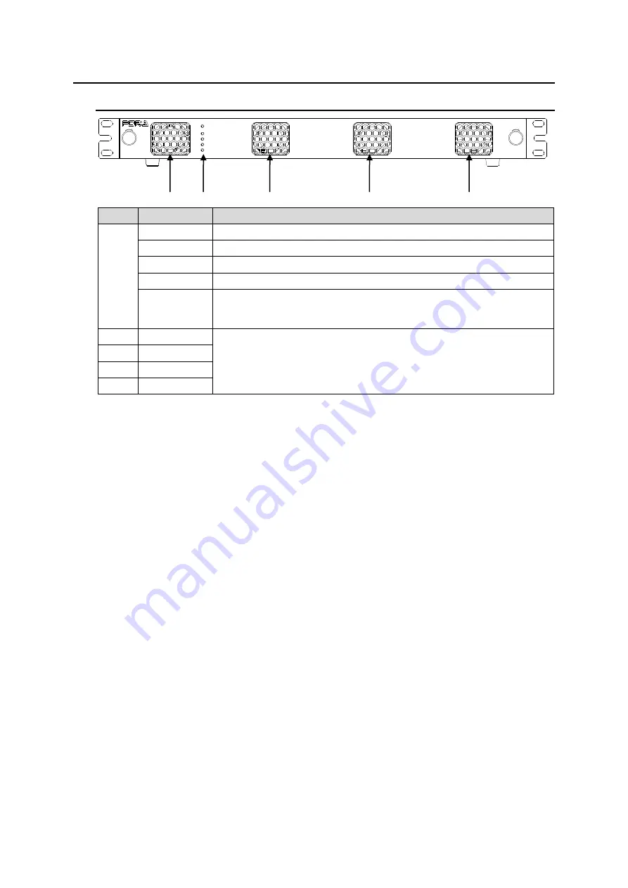
3-1. Front Panel
TEMP
FAN
DC 2
DC 1
ALARM
ON
POWER
USF-105S
UNIVERSAL
SYSTEM FRAME
LOCK
LOCK
No.
Name
Description
(1)
POWER ON
This LED lights green when DC power is supplied normally
DC 1 *
This LED lights red when a voltage error occurs in power module 1.
DC 2 *
This LED lights red when a voltage error occurs in power module 2.
FAN
This LED lights red when at least one fan has stopped.
TEMP
This LED lights red when a temperature error occurs in the power
supply module(s). Lower the environmental temperature to continue
operation.
(2)
FAN1
Cooling fans. Operation status can be monitored by WebGUI Status
Tab. Refer to Sec.9-1.
“Status Tab.”
(3)
FAN2
(4)
FAN3
(5)
FAN4
*
DC 1 and DC 2 become functional when a USF-105PS power supply option is installed.
(1)
(4)
(3)
(2)
(5)


