USF212BS_SETUPGUIDE-E-1.DOCX
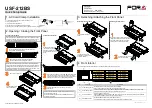
USF-212BS
Quick Setup Guide
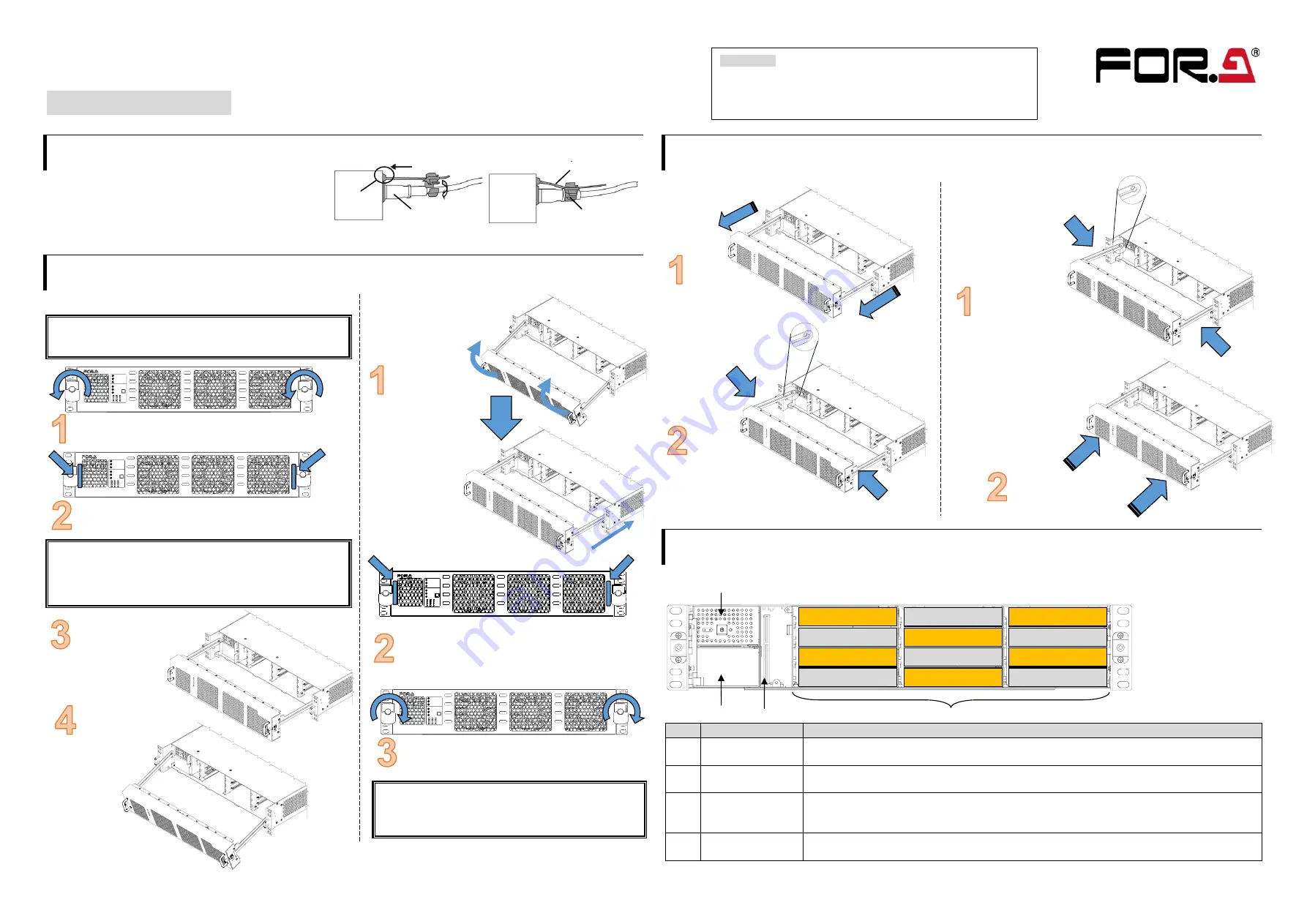
1. AC Cord Clamp Installation
1) Insert the anchor into the hole next to the AC inlet.
2) Plug in the AC cord.
3) Adjust the strap length to fit.
4) Wrap the AC cord clamp around the AC cord.
5) Gently pull on the AC cord to ensure it has been securely plugged in.
2. Opening / Closing the Front Panel
Opening the Front Panel
Closing the Front Panel
The front panel may be difficult to open or close if the USF frame
is placed on a desk, and may be damaged if it is forced to open.
Perform the following steps after setting the frame in a rack.
When the front panel is being opened, one short beep sounds
every 30 seconds to notify the user and after 5 minutes (default
setting), the short beep changes to normal alarm buzzer. When
performing installation or other modification while the power is on,
complete the procedure in a short period of time.
Twenty seconds after the front panel is installed, all LEDs
on the front panel light up.
If not, the front panel has not been installed properly. Re-
install the front panel.
3. Detaching / Attaching the Front Panel
Detaching the Front Panel
Attaching the Front Panel
4. Front Interior
The slot configuration as shown below is revealed when the front panel is removed.
No.
Slot Type
Description
(1)
Power Supply 1 Slot
Dedicated power unit installed in this slot as standard.
Power is supplied when the power supply switch is turned on.
(2)
Power Supply 2 Slot
Slot for redundant power supply USF-212PS. Redundant operation available when optional USF-
212PS is installed. A blank panel will otherwise cover the slot.
(3)
Control Card Slot
Slot for network control card.
Enables SNMP monitoring through LAN ports on the rear panel and alarm output from the ALARM
connector and allows control over the all slot modules..
(4)
USF Module Slots
Dedicated USF module slots. (Front USF modules)
For details on module operation, refer to the respective operation manuals.
Packing list
USF-212BS: 1
AC Cord: 1 set DVD-ROM: 1
Quick Setup Guide: 1 (This guide)
Pull out the front panel.
The front panel rails
can be tilted down.
1
2
3
4
5
6
7
8
10
9
11
12
USF-2 12BS
UNIVERSAL S YSTEM FRAME
GENLOCK 1
POWER ON
GENLOCK 2
ALA RM
DC 1
DC 2
FAN
BUZZER
OFF
1
5
9
2
6
10
3
4
7
8
11
12
1
2
3
4
5
6
7
8
10
9
11
12
USF-2 12BS
UNIVERSAL S YSTEM FRAME
GENLOCK 1
POWER ON
GENLOCK 2
ALA RM
DC 1
DC 2
FAN
BUZZER
OFF
1
5
9
2
6
10
3
4
7
8
11
12
Loosen the two thumbscrews on the front panel by
turning them counterclockwise.
Pull out the front panel using the pull handles.
The fan stops while the front panel is open.
(1)
(2)
(3)
(4)
SLOT1
SLOT2
SLOT3
SLOT4
SLOT5
SLOT6
SLOT7
SLOT8
SLOT9
SLOT10
SLOT11
SLOT12
The front panel can be
detached by gently pushing
both rails inward.
Fully draw out the front
panel.
Grab both handles, tilt up
the front panel until it
aligned and push the front
panel back into the frame
body.
1
2
3
4
5
6
7
8
10
9
11
12
USF-2 12BS
UNIVERSAL S YSTEM FRAME
GENLOCK 1
POWER ON
GENLOCK 2
ALA RM
DC 1
DC 2
FAN
BUZZER
OFF
1
5
9
2
6
10
3
4
7
8
11
12
If the frame is powered on, the POWER LED lights green
and fans begin to work once the front panel is properly
installed. If the LED does not light up, grab both handles
and push the panel until it is tightly fitted into place.
1
2
3
4
5
6
7
8
10
9
11
12
USF-2 12BS
UNIVERSAL S YSTEM FRAME
GENLOCK 1
POWER ON
GENLOCK 2
ALA RM
DC 1
DC 2
FAN
BUZZER
OFF
1
5
9
2
6
10
3
4
7
8
11
12
Tighten two screws in both sides to secure the
front panel.
Gently push rails on both sides inward to
respectively fit the tab into the aperture of
the guide rail. Handle the front panel
carefully so as not to bend the rails.
Push the front panel straight
into the frame body.
http://www.for-a.com/


