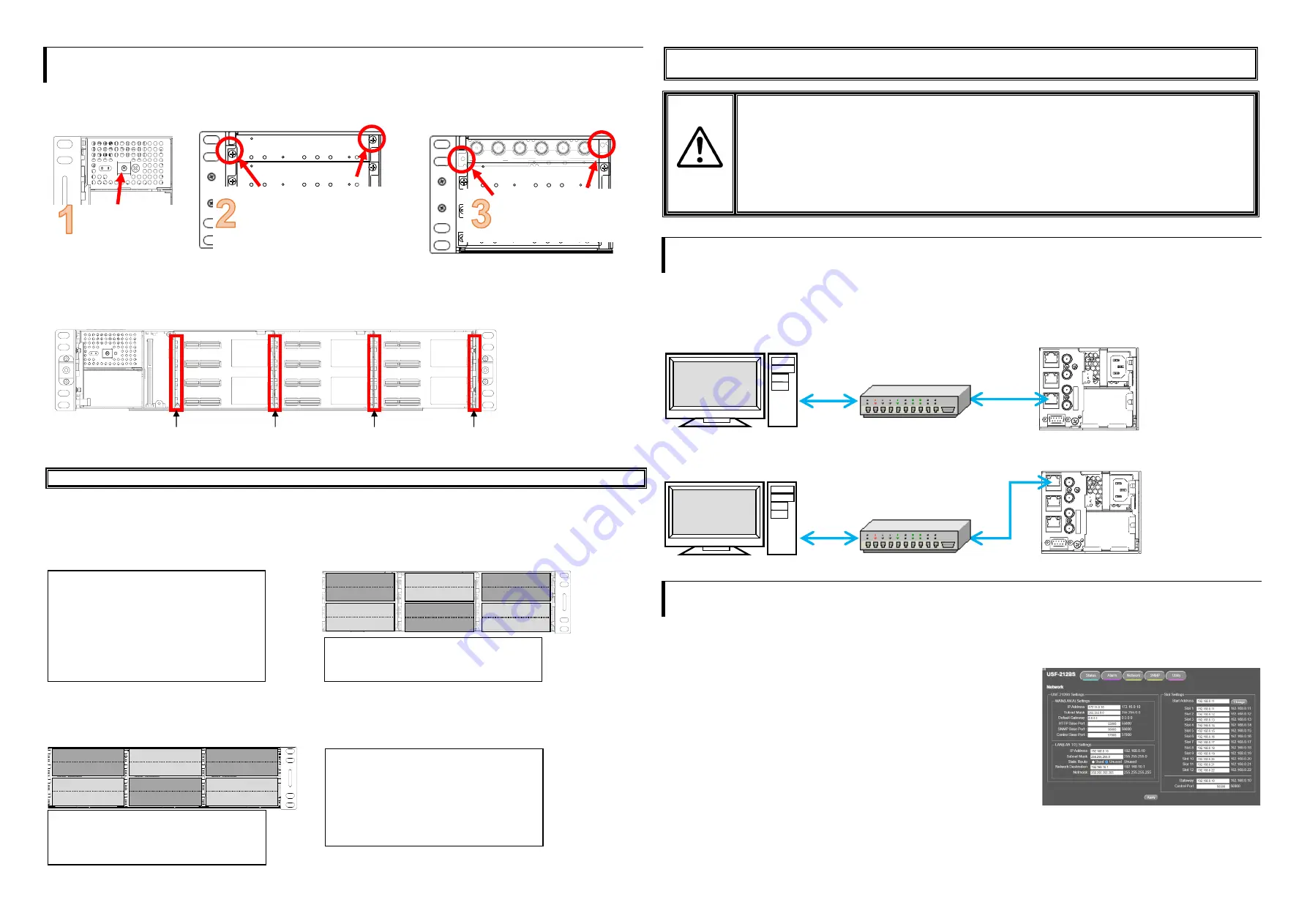
5. USF Module Installation
Module installable slots vary depending on the USF
module type. (See
“
Installation Slots for F
ront
and Rear Modules
”
below.
)
If multiple free slots exist, do not install modules side-by-side but leave slots open to prevent overheating.
The procedure for installing the USF module in Slot 1 is described below as an example.
Installing USF Rear Module
Installing a USF Front Module
* Always
install the rear module first
, then the front module.
(1) Slot 1 is the top slot in the right block of the front panel. (Refer to 4.
“Front Interior”)
(2) Set the front module on the guide rail and carefully insert the front module slowly.
(3) Push the handle until the front module clicks into the connectors.
Always use handles when inserting modules. Otherwise, the modules may be damaged.
Installation Slots for Front and Rear Modules
* Refer to Module Operation Manuals for USF-10IP series.
<TYPE1>
<TYPE2>
Front:
1 slot (All slots)
Front:
1 Slot (Even slots only)
Rear:
1 slot (All slots)
Rear:
2 Slots (Upper and Lower)
<TYPE3>
Front:
1 slot (Odd slots only)
Modules that can be remotely controlled from a PC
Rear:
2 slots (Upper and lower)
require installation of both Processor Control GUI
Launcher and GUI Control Software.
・
USF modules come as front and rear sets. Be sure to install set modules (front and rear) into their proper slots.
・
Install blank panels over free slots to prevent foreign material from entering and overheating the chassis.
IMPORTANT
・
Beware of the occurrence of electrical breakdown in USF Modules.
・
Wear an antistatic wrist strap or equivalent to equalize the electrical potential of the USF-212BS unit and the
worker’s body. Do not touch the PCB wiring or parts legs directly with your fingers while working.
・
Each USF Module can be installed and uninstalled while the power is on in case of emergency. Shut down the
power for non-emergency work.
・
When front module is being installed / uninstalled while the power is on, the front panel is in open state. The fan
will stop during the procedure, so it is essential to complete the installation within a short period and to close the
front panel immediately.
・
Be sure to shut down the power to install and uninstall a control module.
6. Connecting USF-212BS from a PC
USF-212BS can be monitored by the Web GUI or an SNMP Manager and generate alarms to indicate errors or warnings over LAN.
The module provides two LAN connection ports: LAN1/2 or LAN A. Select one of them according to the system.
There are two ways to connect to USF-212BS from a PC: Using LAN1/2 port or LAN A port. Connect to fit your system.
Connecting via LAN A
Connecting via LAN1 or LAN2
Connect to LAN1 or LAN2 on the rear panel. (Example below: LAN1)
7. Network Default Setting
Open the web browser of the PC and input address. A status page as shown opens on the web browser when connection is
established.
Connecting to LAN A:
http://172.16.0.10/
(Factory Setting)
LAN1
または
LAN2
と接続しているとき:
http://192.168.0.10/
(Factory Setting)
IP Address Change
(1) Click the
Network
tab.
(2) Input new IP address into the IP Address box of
WAN (LAN A) Settings
to
change LAN A IP address.
Input new IP address into the IP Address box of
LAN (LAN1/2) Settings
to
change LAN 1/2 IP address.
(3) A confirmation message window opens when you click
Apply
.
Click
OK
in the confirmation window.
(4) Click
Utility
tab, then click
Restart
.
Click
OK
when the restart confirmation window opens.
USF-212
B
S restarts. The new setting is reflected after the restart.
NOTE)
IP addresses are assigned to respective USF-212BS modules installed.
Refer to USF-212BS
operation manual Sec. “USF-212BS WEB GUI” for details on setting IP addresses.
Open the front panel
and shut down the
USF-212BS power
supply.
Slot 1 is the top slot in the left module
block on the rear panel. Remove the
blank panel by detaching the two
screws on both ends. Keep the blank
panel and screws in a safe place after
removal.
3G/HD/SD SDI IN
USF-1043FS
1
2
1
2
3
4
3G/HD/SD SDI OUT
Insert the rear module into
the slot and fasten both
supplied screws.
Installable modules
105DADA
402AADC
108ADA
1013MUX
1040VEA
1013DEMUX
1053DDA
1043FS
105DDA-12G
105FS-12G
105DDA-12GA
1043VM
204ADAC
80SDICS
Installable modules:
1100VEA
1043SS
1044UDC
1043VTG-LI
SLOT 12
SLOT 2
SLOT 4
SLOT 6
SLOT 8
SLOT 10
Installable modules:
106UDC-12G
101MDX4-12G
106DC-12G
101MDX8-12G
106TICO-12G
111DDA-12G
SLOT 1
SLOT 3
SLOT 5
SLOT 7
SLOT 11
SLOT 9
Available modules:
106UDC-12G
106DC-12G
101MDX4-12G
101MDX8-12G
105FS-12G
106TICO-12G
See the Processor Control GUI Launcher
Operation Manual for details
PCB Guide Rail
PCB Guide Rail
PCB Guide Rail
PCB Guide Rail
USF-212BS
ALARM
S
E
R
.N
O
.
2
AC
10
0-
24
0V
5
0/
60
Hz
I
N
AC
10
0-
24
0V
5
0/
60
Hz
IN
1
GENLOCK 2
GENLOCK 1
LAN A
LAN 2
LAN 1
LAN 1/2 IP Address
Factory default
192.168.0.10
Slot1 to 12 IP Address
Factory default
192.168.0.11
to 192.168.0.22
LAN1 LED (LAN2
LED)
Lit Green
: Connected
Flashing Orange
: Transmitting
and receiving data
USF-212BS Rear Panel
Web browser
SNMP manager
USF-212BS
ALARM
S
E
R
.N
O
.
2
AC
10
0-
24
0V
5
0/
60
Hz
I
N
AC
10
0-
24
0V
5
0/
60
Hz
IN
1
GENLOCK 2
GENLOCK 1
LAN A
LAN 2
LAN 1
LAN A IP Address
Factory default
172.16.0.10
LAN A
LED
Lit Green
: Connected
Flashing Orange
: Transmitting
and receiving data
USF-212BS Rear Panel
Web browser
SNMP manager


