background image

.     

Carefully lift the fan assembly onto the mounting

       bracket.

.     

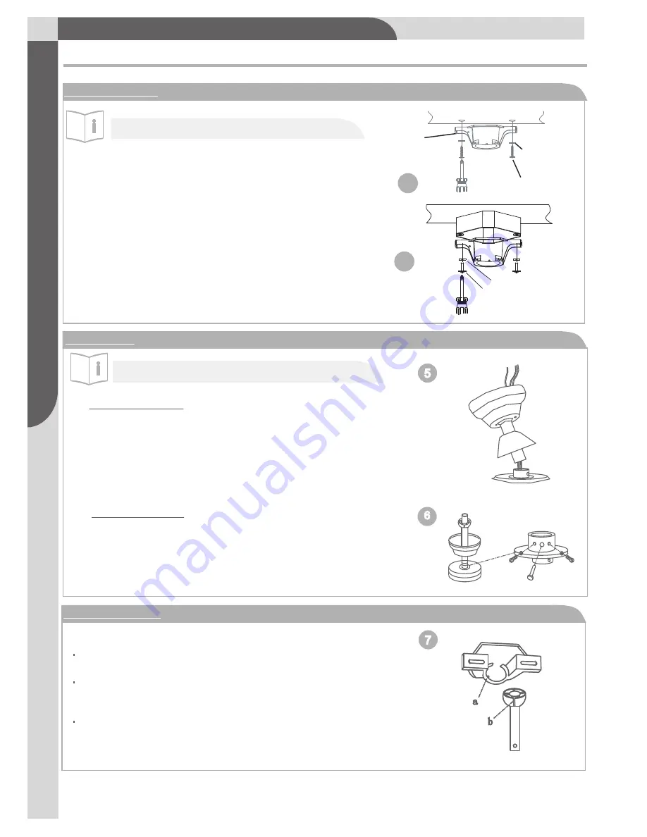
Rotate the fan until the notch  (b) on the aluminium

       ball fits against the ridge (a) on the mounting
       bracket (see Fig. 7).
.     With the mounting bracket holding the fan assembly,

4

a

b

7

6

5

1.Mounting bracket

Installation

Toll-free: 877-483-6759

       •  model n

o. 052-2230-6

As

se

m

bl

y

ASSEMBLY

Note

: The mounting bracket depicted will vary

depending on the model .

.   

2.Drop-mount

Note

: Canopy picture may vary from product for

some styles of ceiling fans.

Downrod assembly

.   

Loosen the two downrod set screws and remove

       the clip and connection pin from the

        downrod coupling. Insert the downrod through

        canopy and flange cover,pull lead wires through

        downrod(see Fig. 5).

Securing assembly

.     Insert downrod into downrod coupling. Make sure to

      align holes in downrod with the hole in the coupling.

      Insert the clip into the connection pin until it snaps

      into place. Tighten the screws in the downrod coupling

      (see Fig. 6).

3 Hands free wiring

follow wiring instructions (step 4).

Outlet box screw 

Lock washer

4b

.  Remove the four sets of side screws from mounting

bracket and save for future use.


Wooden ceiling

Drill two mounting holes in the ceiling joist.Securely 

 attach the mounting bracket to the ceiling or 

 wooden ceiling as indicated below (fig. 4a).


Normal masonry ceiling

Securely attach the mounting bracket to

an outlet box marked “ 

Acceptable for Fan

Support

”, using the supplied outlet box 

screws with lock washers (see Fig. 4b).


4a


Mounting 
  bracket

Flat 

washer

wood screw

Summary of Contents for 052-2230-6

Page 1: ...read and understand this manual before any assembly Before Toll free 1 877 483 6759 V5 2016 beginning assembly of products make sure all parts are present Compare parts with exploded view If any parts is missing or if you have any questions contact customer service at 877 483 6759 ...

Page 2: ...FULLY Toll free 877 483 6759 model no 052 2230 6 1 2 2 Tools required for assembly 3 Assembly 3 Operation 7 Maintenance 8 Care and cleaning 8 Troubleshooting 8 Environmental protection 9 Warranty 10 Exploded view Rules for safe installation Important safety instructions ...

Page 3: ...cket Downrod Assemble Canopy Flange Cover Motor Assemble Switch Housing Light Kit 1 5 1 1 1 1 1 1 No Description Qty I Blade Arm 5 J Glass Shade 1 K Bulbs E12x60W 2 L Remote Control 1 M Receiver 1 N Parts Pack 1 O Balance Pack 1 EXPLODED VIEW A B C D E F G H I J K M L N O ...

Page 4: ...e or noncompliance with the instructions CAUTION To avoid possible electric shock be sure electricity at the fuse box or the circuit breaker is turned off before wiring All wiring must be done in accordance with national and local wiring codes Consult a qualified electrician to ensure correct branch circuit conductor Follow the recommended instructions for the proper method of wiring for the new c...

Page 5: ...ie ASSEMBLY Preparing for installation Getting ready Unpack and inspect carefully to make sure all parts are included and not damaged see Fig 1 Lay all pieces out on a working space possible electrical shock see Fig 2 Choosing a location for the ceiling fan 32 81 3 cm from adjacent walls or obstructions Choose a location where there is a high enough ceiling clearance at least 2 1 m from the floor ...

Page 6: ...flange cover pull lead wires through downrod see Fig 5 Securing assembly Insert downrod into downrod coupling Make sure to align holes in downrod with the hole in the coupling Insert the clip into the connection pin until it snaps into place Tighten the screws in the downrod coupling see Fig 6 3 Hands free wiring follow wiring instructions step 4 Outlet box screw Lock washer 4b Remove the four set...

Page 7: ...eiver and bracket Installing Receiver Assembly Remote and Receiver Pairing Codes are set by pushing the location of the dip switches located on the transmitter and receiver up or down It is important that the code used for both the remote and receiver are identical for the two devices to be able to communicate otherwise the remote will not be able to control the fan If you plan to install more tha...

Page 8: ...no bare wire or wire strands are visible after making connections Place green and white connections on opposite side of box from the black and blue if applicable connections hanger ball Downrod Receiver Antenna DO NOTCUT OR SPLICE 3 4 5 6 1 2 hanger ball to the ground wire bare or ...

Page 9: ...read light kit assembly onto switch housing cap Tighten securely with lock washer and hex nut see Fig 12a Connect the wire inside the switch housing cap by snapping the male and female connectors together Match white wires together and blue wire to black wire together Screw on light kit assembly and switch housing with 3 screws previously removed see Fig 12b 9 Mounting light kit glass Install 2X60...

Page 10: ... rotation while the fan blades are in motion before setting the switch to the desired rotation direction either forward or reverse Reverse Forward Switch housing Reverse switch 9 V B a tt e r y Install the 9 V battery included To prevent damage to transmitter remove the battery if not used for long periods Restore power to ceiling fan and test for proper operation The fan remote control controls t...

Page 11: ...rt Possible reason Blade screws are loose The mounting bracket or canopy is loose Screws securing decorative housing to hanger are loose Lamp shades or bulbs are loose Screws securing downrod to hanger are loose Wire connectors are vibrating against the inside of canopy Light kit or light bulb is not firmly attached Canopy is rattling against ceiling Motor housing screws have come loose Fuse or ci...

Page 12: ...s recommended in warm weather reverse slide switch rotation to stop Change the forward Place fan in the centre of the room so there is at least 12 30cm between the end of the blades and walls or other obstructions Make sure that screws which attach fan blade clips to motor are fastened and tightened Tighten screws of fan blade to blade clip securely Ensure that canopy and mounting bracket are tigh...

Page 13: ...less otherwise specified in writing g This warranty will not apply to any product or part thereof ifany part from another manufacturer is installed therein or any repairs or alterations have been made or attempted by unauthorized persons h This warranty will not apply to normal deterioration of the exterior finish such as but not limited to scratches dents paint chips or to any corrosion or discol...

Reviews: