9
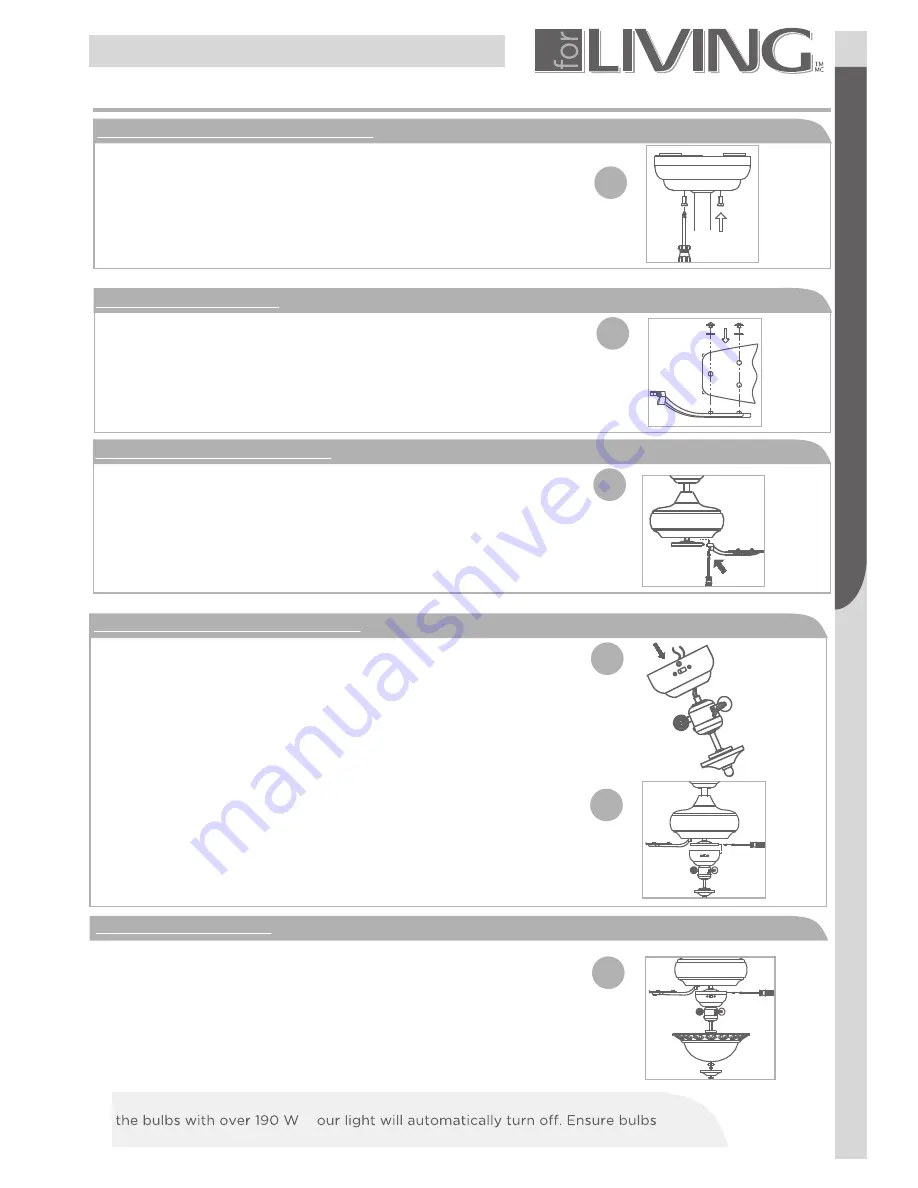
5. Attach assembly to mounting bracket
. Unhook the assembly from the mounting bracket.
. Hold the assembly by the canopy and raise up to
align the two holes in the canopy with the holes in
the mounting bracket.
. Tighten the loosened screws. Now re-secure the
screws and washers which were removed(see Fig. 9).
ASSEMBLY
Assembly
7
11
12a
12b
13
7. Attach blade assembly to motor
. If there are plastic tabs shaped like bottle caps, remove
and discard them. These are stabilizers that protect the
motor during shipping.
. Remove blade bracket screws on the bottom
of the motor and use them to attach the blade
assembly to the motor. Ensure th t the screws
are tightened(see Fig. 11).
8. Connect switch housing and light kit
. Remove and retain 3 screws from switch
housing. Remove plastic button in centre of
switch housing cap. Thread light kit assembly
onto switch housing cap. Tighten securely with
lock washer and hex nut.(see Fig. 12a).
. Connect the wire inside the switch housing
cap by snapping the male and female
connectors together. Match white wires
together and blue wire to black wire together. Sc
r e w
on light kit assembly and switch housing
with 3 screws previously removed.
(see Fig. 12b)
9.Mounting light kit glass
. Install 2X60 W candelabra-base bulbs (included).
Install light kit glass to the light kit assembly
with rubber washer, flat washer and hex nut.
DO NOT over tighten. Install cap and screw finial
onto the light kit assembly.(see Fig. 13).
Your fan has an energy-saving wattage limiter. If you replace
7. Attach blade as
to mot
10
6. Blade and blade bracket
. Using the fan blade screws and washers,
attach the fan blades(see Fig. 10).
Note
: This ceiling fan includes 5 dual-finished
blades. Depending on personal preference,
choose the side that best suits the decor or
furniture of your room.
IMPORTANT NOTE:
wattage are always below 190 W !
,
y


