background image

Assembly 


12  

Model No. 085-1523-8


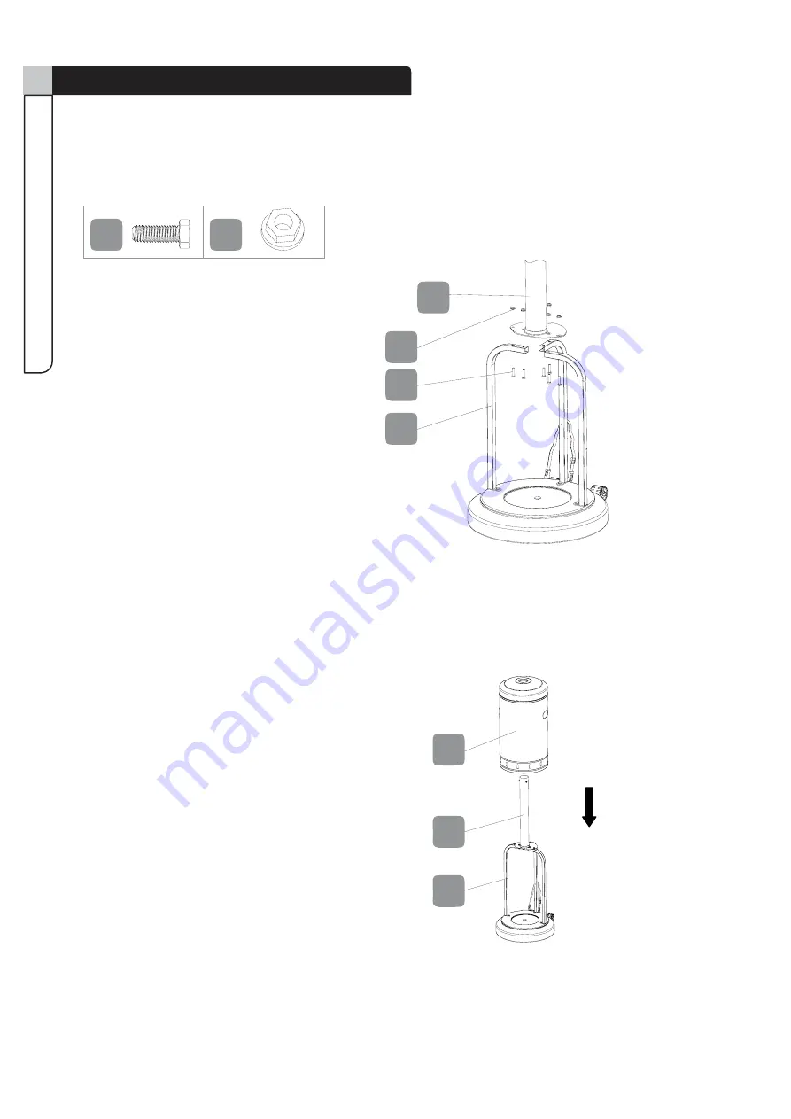
Step 3 

Requires


6, 8, I, J 

Attach Lower Pole Assembly (6) onto the Support Brackets (8) using M6 x 35 mm Bolts (I) and M6 Nuts (J).  


A B


Shown at actual size


11


B


G  

C


Step 4 

Requires 

6, 7 

Load the Cylinder Housing (7) onto the Lower Pole Assembly (6), and slide the Cylinder Housing (7) down.  


1


J

Summary of Contents for 085-1523-8

Page 1: ...Patio Heater Model No 085 1523 8 Instruction Manual Toll free 1 877 483 6759 IMPORTANT Please read this manual carefullybefore beginning assembly ofthis product Keepthis manual forfuture reference ...

Page 2: ...Imported by Trileaf Distribution Trifeuil Toronto Canada M4S 2B8 ...

Page 3: ...e and Maintenance 18 Troubleshooting 20 Warranty 20 Certification CSA Height Overall 80 1 2 204 cm Reflector Diameter 31 1 2 80 cm Rated Heat Input 40 000 BTU hr Fuel Propane LP Gas Supply 20 lb LP Gas cylinder Manifold Pressure 11 W C Injector Size diameter 1 92 mm Safety Features Thermocouple Tilt Switch Gas Supply Pressure Max 150 PSI Min 5 PSI Technical Specifications 3 Table of Contents ...

Page 4: ...se with regulator assembly out of pathways where people may trip over it or in areas where the hose will not be subjected to accidental damage Materials or items when stored under the heater will be subjected to intense heat and could be seriously damaged Clothing or other flammable materials should not be hung on the heater or placed on under or near the heater Children and adults should be alert...

Page 5: ...pecifications for LP gas cylinders of the U S Department of Transportation of Dangerous Goods and Commission CAN CSA B339 as applicable b Provided with a listed overfilling prevention device and c Provided with a cylinder connection device compatible with the connection for the appliance Disconnect the cylinder when the appliance is not in use Storage of an appliance indoors is permissible only if...

Page 6: ...oses you to lead a chemical known to the State of California to cause cancer and birth defects or other reproductive harm Wash hands after handling c This product contains chemicals including lead and lead compounds known by the State of California to cause cancer reproductive harm or other birth defects d Wash your hands after using this product 6 WARNING RETAIN FOR FUTURE REFERENCE AND READ CARE...

Page 7: ... X 8mm Silver Bolt x12 5 mm Washer x12 Reflector Spacer x3 M8 X 15mm Bolt x2 M5 Nut x12 M8 Nut x2 M6 X 15mm Bolt x3 M6 X 35mm Bolt x6 M6 Nut x6 M5 X 8mm Black Bolt x6 Wing Nut x3 F F JJ HH B B AA DD K K II CC EE G G 2 3 1 3 2 3 3 3 4 3 5 4 3 11 5 6 7 8 10 13 9 12 14 1 ...

Page 8: ...ome 1 2 KD Dome 4 6 Lower Pole Assembly 1 12 Wheel Assembly 1 3 Burner Assembly 1 3 2 Thermocouple 1 3 3 Ignition Pin 1 3 4 Valve Shroud Cover 1 3 5 Tilt Switch 1 4 Control Knob 1 3 1 Burner Chamber Assembly 1 11 Regulator Hose Assembly 1 13 Weight Plate 1 14 Hardware Pack 1 F B H J A I K G C E D 9 Cylinder Strap 1 ...

Page 9: ...hown at actual size I M6 x 35 mm Bolt 6 Shown at actual size J M6 Nut 6 Shown at actual size D M5 x 8 mm Black Bolt 6 Shown at actual size E M6 x 15 mm Bolt 3 Shown at actual size F M5 x 8 mm Silver Bolt 12 Shown at actual size A M8 x 15 mm Bolt 2 Shown at actual size B Reflector Spacer 3 Shown at actual size C M8 Nut 2 ...

Page 10: ...th packaging contents list If any part is missing or if you have questions contact the service centre at 1 877 483 6759 toll free Place all parts from the box in a cleared area and position them on the floor in front of you Remove all packing materials and place them back into the box Do not dispose of the packing materials until assembly is complete Read each step carefully before beginning any as...

Page 11: ...own at actual size 4 4 4 4 4 4 4 3 4 B A Step 2 Requires 8 10 E Reverse the Base 10 and attach three Support Brackets 8 to the Base 10 using M6 x 15 mm Bolts E A B Shown at actual size B 6 6 7 7 A 10 11 A C C 10 12 A E 10 E 9 8 12 Note Install the Support Bracket 8 with Cylinder Strap 9 into the hole next to the Wheel Assembly 12 ...

Page 12: ... Lower Pole Assembly 6 onto the Support Brackets 8 using M6 x 35 mm Bolts I and M6 Nuts J A B Shown at actual size 5 A 11 B G C Step 4 Requires 6 7 Load the Cylinder Housing 7 onto the Lower Pole Assembly 6 and slide the Cylinder Housing 7 down 1 I J 6 J I 8 8 7 6 ...

Page 13: ...nect the Burner Assembly 3 to the Upper Pole 5 6a Feed the Regulator Hose Assembly 11 into and through the Upper Pole 5 6b Screw Burner Assembly 3 onto Upper Pole 5 until the holes on bottom of Burner Assembly 3 are aligned to the holes on top of Upper Pole 5 Fix them by using three M5 x 8 mm Black Bolts D Ensure they are fully tightened A B Shown at actual size B GG B B 3 D 3 11 5 D 13 ...

Page 14: ...oles on Upper Pole 5 are aligned to the holes on top of Lower Pole Assembly 6 Fix them by using three M5 x 8 mm Black Bolts D Ensure they are fully tightened A B Shown at actual size A 4 3 Step 8 Requires 1 2 G H F Attach the four KD Domes 2 using M5 x 8 mm Silver Bolts F M5 Nuts G and 5 mm Washers H Then complete dome assembly by attaching Top Dome 1 to KD Domes 2 with M5 x 8 mm Bolts F M5 Nuts G...

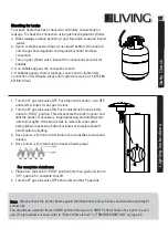
Page 15: ...O NOT USE ANY HAND TOOLS TO MAKE THIS CONNECTION Be careful not to cross threads when screwing in fitting To disconnect the LP Gas cylinder first make sure the cylinder valve is OFF then turn the knob on the regulator counterclockwise until it is loose Warning Before connecting be sure that there is no debris caught in the head of the LP gas cylinder the head of the regulator valve or in the head ...

Page 16: ...16 Model No 085 1523 8 Step 10 Requires 7 9 Attach Cylinder Strap 9 to stabilize the cylinder Then slide the Cylinder Housing 7 to complete installation Assembly 9 7 ...

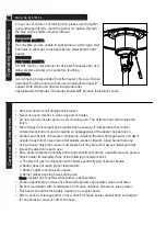
Page 17: ...ON Push control knob in and slowly rotate to HIGH position This will activate the built in igniter and light the burner If necessary keep depressing and rotating knob until burner lights If the burner fails to remain lit or becomes extinguished repeat step 2 after 5 minutes of complete shutoff period before relighting 3 Once burner is lit hold control knob in for at least 30 seconds and release 4 ...

Page 18: ...nt burners and circulating air passageways of the heater be kept clean y Spiders and insects can create a dangerous condition that may damage heater or make it unsafe Keep burner area clean of all spiders webs or insects Clean burner holes by using a heavy duty pipe cleaner Compressed air may help clear away smaller particles y Inspect heater before each use y Have heater inspected annually and re...

Page 19: ...eways clean Signs of possible blockage include Gas odour with extreme yellow tipping of flame Heater does NOT reach the desired temperature Heater glow is excessively uneven Heater makes popping noises Note In a salt air environment such as near an ocean corrosion occurs more quickly than normal Frequently check for corroded areas and repair them promptly Storage Between uses or during periods of ...

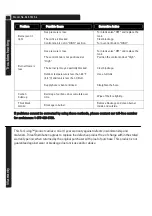
Page 20: ... pressure is low The orifice is blocked Control knob is not in HIGH position Turn tank valve OFF and replace the tank Clear blockage Turn control knob to HIGH Burner flame is low Gas pressure is low The control knob is not positioned at High The burner jet may be partially blocked Outdoor temperature is less than 40 F 4 4 C and tank is less than 1 4 full Supply hose is bent or kinked Turn tank val...

Reviews: