Centellis CT Series 16000 User’s Manual
Installation
20000325 420 000 AB
Page 11
2.6
Power Controls
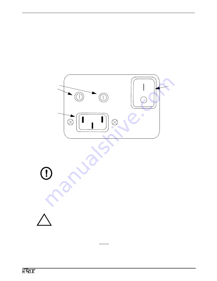
The Centellis CT Series 16000 chassis has one AC input power connector and an on/off power
switch located at the lower left back of the chassis. The “
” symbol at the top of the green switch
indicates the on position; the “ O ” on the bottom half of the switch indicates the off position. Two
user-replaceable 7A fuses are provided to the left of the power switch. The unit’s power cord is de-
tachable. See Figure 6 for an illustration of these controls.
Input voltage for the two AC power supplies is selectable via external slide switches.
Figure 6: Chassis Power Controls (Lower Left, Rear)
IMPORTANT
The socket outlet that the system is connected to must be installed near the equipment
and readily accessible.
2.7
Board Switches
The switches of installed boards are always accessible from the front of the chassis. Consult the
appropriate CPU board hardware user’s manual to adjust the board switches.
CAUTION
!
With the exception of lithium batteries installed on a board in this system, the
Centellis system is designed to be maintenance-free. The lithium battery in the
RTC/NVRAM provides a data retention capability of ten years (actual battery use);
after this usage period, the Ethernet address, the host ID address, and all other
RTC/NVRAM contents may be lost.
Contact Force Computers before ten years of actual battery use have elapsed.
There is a danger of explosion if the battery is incorrectly replaced. Replace the
On/Off
Switch
Power
Connector
Fuses


