Installation Guide
SPARC/CPU-5CE
Page 10
FORCE COMPUTERS
1.5.9
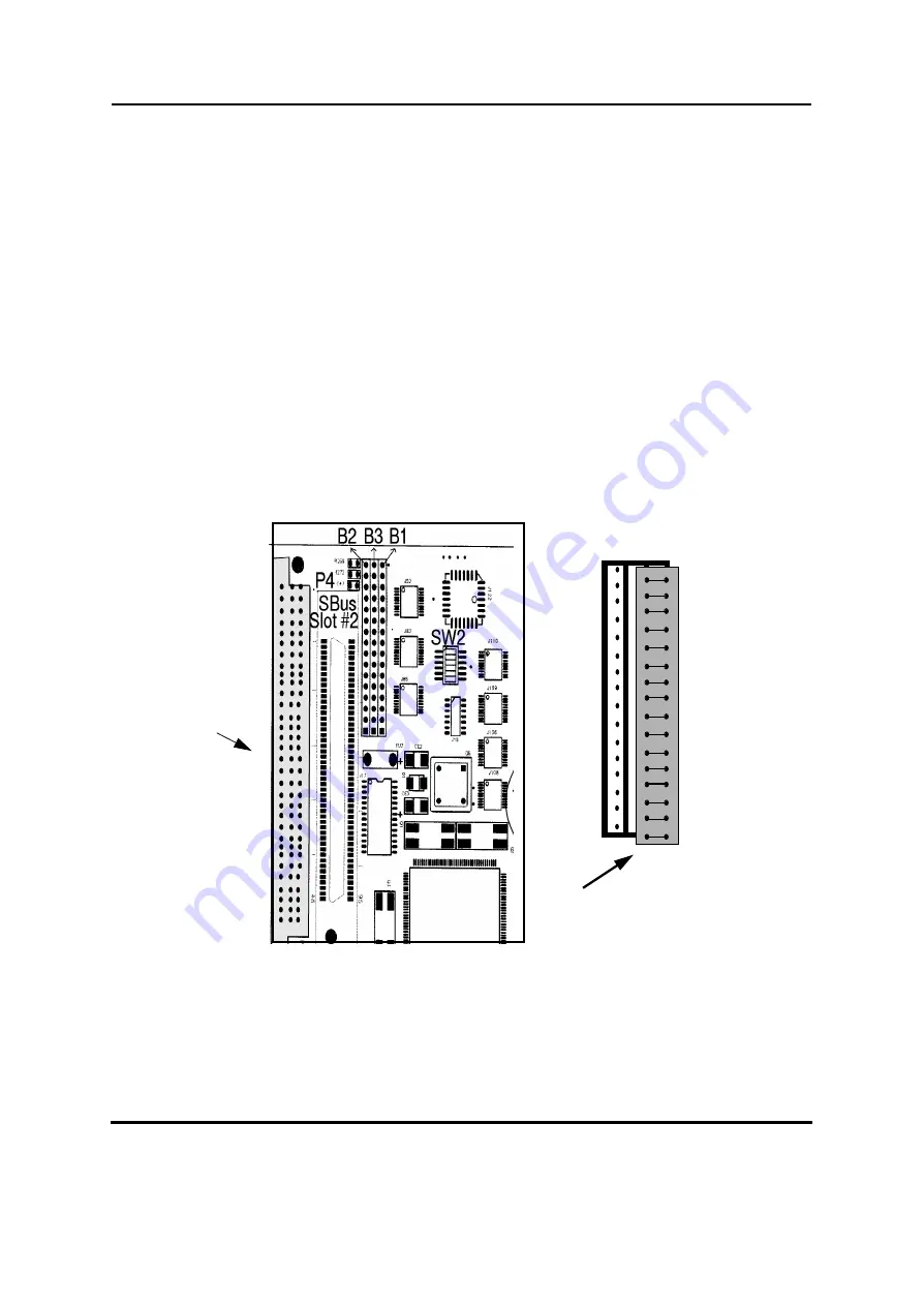
Parallel Port or Floppy Interface via VME P2 Connector
Via a 16-pin configuration switch matrix, it is possible for either the parallel port interface or
the floppy interface to be available on the VME P2 connector.
The default setting enables the floppy interface via the VME P2 connector, with the
configuration switch matrix plugged into B2 and B3. This means, of course, that by default the
parallel port interface is not available via the VMEbus P2 connector.
To enable the parallel port interface via the VME P2 connector, plug the configuration switch
matrix in sockets B1 and B3. The following drawing shows this configuration.
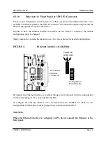
FIGURE 3.
Parallel Port Interface Via VME P2 Connector
The switch matrix plugs into connectors B1 and B3 and the parallel port is accessible through
the VMEbus P2 connector.
VMEbus P2
Connector
B2 B3 B1
Switch Matrix
connected to B3 & B1
Enlarged View of CPU-5CE
Summary of Contents for SPARC CPU-3CE
Page 4: ...Table of Contents SPARC CPU 5CE Installation Guide Page ii FORCE COMPUTERS...
Page 6: ...List of Figures SPARC CPU 5CE Installation Guide Page iv FORCE COMPUTERS...
Page 8: ...List of Tables SPARC CPU 5CE Installation Guide Page vi FORCE COMPUTERS...
Page 11: ...FORCE COMPUTERS Page 3 SSPARC CPU 5CE Installation Guide FIGURE 1 Diagram of the CPU 5CE...
Page 48: ...Installation Guide SPARC CPU 5CE Page 40 FORCE COMPUTERS...


