4
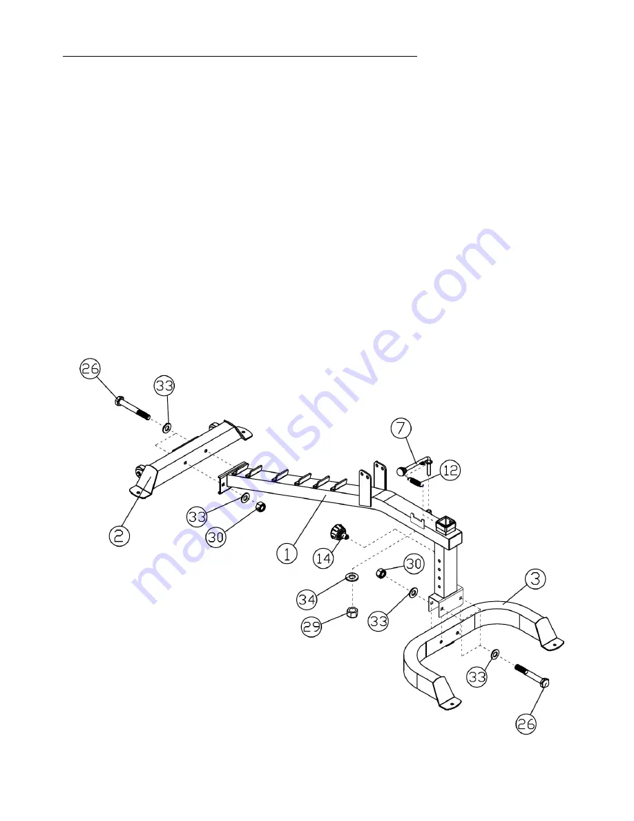
ASSEMBLY DIAGRAM 1
REMEMBER: Only hand tighten all nuts and bolts until whole F-FID is assembled
1.
Ensuring correct orientation, attach the front of the MAIN FRAME (1) to the FRONT BASE FRAME (3) using
two HEX BOLT M10X75 (26), four WASHER10 (33) and two AIRCRAFT NUT M10 (30)
2.
Attach the WHEELS (22) to the back of the REAR BASE FRAME (2) using a HEX BOLT M8X45 (24), two
WASHER8 (32) and an AIRCRAFT NUT M8 (31) on each wheel.
(
See the exploded diagram for more detail,
skip this step if pre-assembled)
3.
Ensuring correct orientation, attach the rear of the MAIN FRAME (1) to the REAR BASE FRAME (2) using two
HEX BOLT M10X75 (26), four WASHER10 (33) and two AIRCRAFT NUT M10 (30)
4.
Insert a LOCK KNOB (14) into the rear of the front post on the MAIN FRAME (1)
5.
Connect the HANDBALL (37) to the ADJUSTMENT SUPPORT (7) and attach to the top of the MAIN FRAME (1)
using a WASHER12 (34) and an AIRCRAFT NUT M12 (29)
6.
Attach the TENSILE SPRING (12) to the top of the MAIN FRAME (1)
7.
Insert a SLEEVE (20) into the top of the front post on the MAIN FRAME (1) (
See the exploded diagram for
more detail, skip this step if pre-assembled)
Summary of Contents for F-FID
Page 7: ...7 EXPLODED DIAGRAM F FID...
Page 8: ...8 HARDWARE F FID...


