background image

M-6007-Z460FFT(FRT) 

Crate Engine 

GUIDE 


NO PART OF THIS DOCUMENT MAY BE REPRODUCED WITHOUT PRIOR AGREEMENT AND WRITTEN PERMISSION OF  

FORD PERFORMANCE PARTS. 

Techline 1-800-367-3788 

Page 17 of 24   


IS-1850-0636


Factory Ford shop manuals are available from Helm Publications, 1-800-782-4356


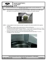
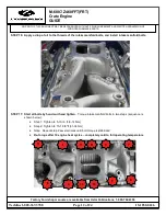
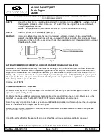
STEP 8:


Using the vertical line on the distributor shaft and the noted dimension (see 

STEP 4

), roughly plot where 

the original roll pinhole is located. Drill a new .125" hole 90˚ from the original hole, above or below it, 

through the gear and the shaft. 

NOTE:


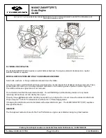
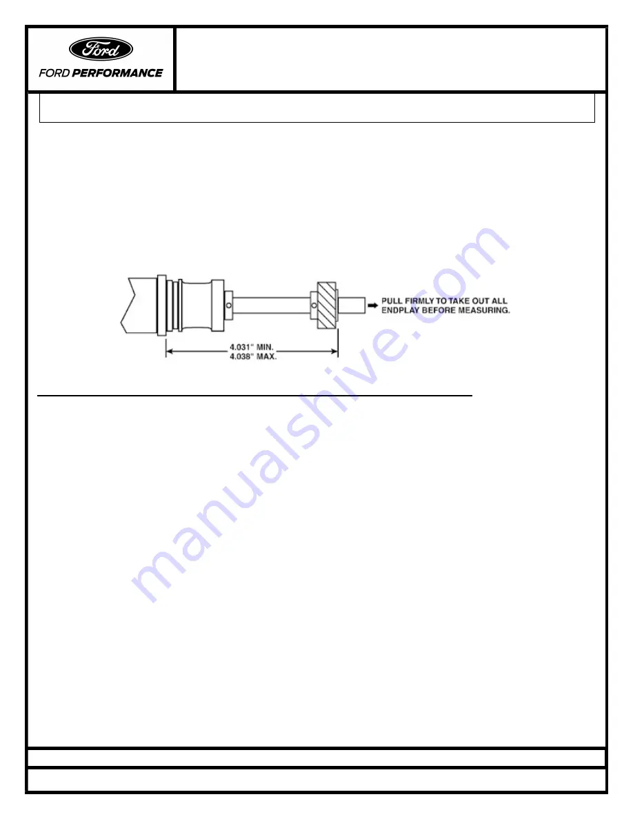
It is important that the dimensions called out in Fig. 1 are maintained while drilling. 


STEP 9:


Insert roll pin and check dimensions (see Fig. 1). 


WARNING:


Improper installation may force the gear down against the block or it may be held up away from the 

support in the block. Both conditions will cause damage to the block and or the block and gears. Proper 

installation and the cut on the gears will pull the distributor gear down against the support (distributor gear 

thrust face) in the block. 


Fig. 1 


ALTERNATIVE METHOD OF VERIFYING CORRECT DISTRIBUTOR GEAR INSTALLATION: 


After 

STEP 7

, install distributor assembly in the block you are using. Timing chain set and camshaft must be removed. 

With the aluminum distributor housing fully seated against the block, verify that the distributor gear can be lifted off the 

support in the block at least .005". Next pull the distributor gear down against the support in the block and hold it there. 

Pull up on the aluminum distributor housing and verify that you can lift it up at least .005" while holding the gear against 

the support in the block. This procedure will confirm that the gear is not being forced down against the support and not 

being held up off the support in the block. 


Continue with 

STEP 8


COMMON DISTRIBUTOR PROBLEMS 


Distributors with very little or no shaft endplay. This condition may force the gear against the support in the block or hold it 

up off the support, causing damage. 


Distributors that have a different material gear than advertised. It is important to run the correct distributor gear for the 

camshaft that you are using. The M-6007-Z460FFT(FRT) requires a distributor with a steel gear. 


Some heavy-duty oil pump drive shafts may not allow an EFI distributor to slide down far enough over the oil pump drive 

shaft. EFI distributors have a longer shaft below the gear. 


Running an high volume oil pump with production bearing clearances can cause excessive oil pressure and possible 

premature distributor gear wear. 


Inspect the surface finish on the gear teeth, a rough surface finish will cause premature distributor gear wear. 


Summary of Contents for M-6007-Z460FFT

Page 1: ...UMENT MAY BE REPRODUCED WITHOUT PRIOR AGREEMENT AND WRITTEN PERMISSION OF FORD PERFORMANCE PARTS Techline 1 800 367 3788 Page 1 of 24 IS 1850 0636 Factory Ford shop manuals are available from Helm Pub...

Page 2: ...ble from Helm Publications 1 800 782 4356 Table of Contents Warranty Intake Manifold Installation Instructions Tech Specifications Engine Installation and Tuning Tips Oiling System o Priming o Oil Pan...

Page 3: ...ebec none of the limitations and exclusions below will exclude or restrict the warranty provided for in Sections 37 and 38 of the Quebec Consumer Protection Act This warranty does not preclude the ope...

Page 4: ...drawn into cylinders or the crankcase Towing shipping rental vehicles loss of time inconvenience loss of use or other economic loss to the extent allowed by law except in the Province of Quebec where...

Page 5: ...E DUE TO PISTON SCUFFING DETONATION IMPROPER COMBUSTION OIL LEAKS COOLANT LEAKS OIL CONSUMPTION NOTE READ THRU COMPLETE INSTRUCTIONS BEFORE STARTING STEP 1 Below is a picture of everything needed to a...

Page 6: ...deeper if necessary Check the carburetor throttle body gasket alignment Also look at the gasket surfaces for nicks and damage raised surfaces on the flanges can prevent sealing Minor raised imperfect...

Page 7: ...asteners STEP 6 A pre assembly mock up is required to check the proper fit of the intake manifold to the long block assembly Place the intake manifold on the long block without the intake manifold gas...

Page 8: ...1 800 782 4356 STEP 7 The minimum thread engagement required for the intake manifold bolts is 625 or 5 8 Too little thread engagement can damage threads and strip out Thread engagement must be checke...

Page 9: ...2 4356 STEP 9 Two different types of sealers are used during intake manifold installation 1 a contact cement type such as Gasgacinch or High Tack and 2 Silicone The recommended silicone is Motorcraft...

Page 10: ...8 Page 10 of 24 IS 1850 0636 Factory Ford shop manuals are available from Helm Publications 1 800 782 4356 STEP 11 Install EGR gasket or block off depending on intake manifold style If the manifold do...

Page 11: ...PARTS Techline 1 800 367 3788 Page 11 of 24 IS 1850 0636 Factory Ford shop manuals are available from Helm Publications 1 800 782 4356 STEP 13 Apply a thick layer of silicone onto the end rails of th...

Page 12: ...4356 STEP 16 Apply a drop of oil to the threads of the intake manifold bolts and install intake manifold bolts STEP 17 Start all bolts by hand and hand tighten Torque intake manifold bolts in two step...

Page 13: ...Camshaft Lobe Separation 110 Camshaft Duration 242 248 050 lift int ex Camshaft Lift 594 618 int ex Cylinder Head M 6049 Z Aluminum Chamber Volume 63cc Valve Diameter Int Ex 2 020 Int 1 600 Ex Compres...

Page 14: ...riming the oiling system before starting a new engine is crucial to engine life This is important on initial start up of a new engine or if the engine has not been run for an extended period of time P...

Page 15: ...screen at all times Is the pickup screen the proper distance from the bottom of the oil pan If the oil pickup screen is too close to the bottom of the oil pan it can cause cavitation If it is too far...

Page 16: ...g can damage pistons rod bearings head gaskets and many other engine parts Typical total mechanical advance timing at 4000 rpm for Ford Performance crate engines M 6007 Z460FFT FRT is 30 BTDC 91 octan...

Page 17: ...emoved With the aluminum distributor housing fully seated against the block verify that the distributor gear can be lifted off the support in the block at least 005 Next pull the distributor gear down...

Page 18: ...til the drive gear drops into position Sometimes rotation of the oil pump driveshaft is required to allow the distributor to drop all the way STEP 5 Verify rotor blade is pointing at the 1 mark on the...

Page 19: ...C also have an effect Here are some examples of a Holley 750 CFM 4V Jetting example Jetting Jetting Octane Temp Elevation Front Rear 94 80 F Sea level 81 86 Aviation 100LL 80 F Sea level 81 84 110 Rac...

Page 20: ...ots will promote improper combustion which can cause engine failure Improper pulley size makes the fan and water pump turn too slow or too fast Production water pumps normally run at 20 over engine sp...

Page 21: ...is installed for all manual transmission applications If using an automatic transmission be sure the pilot bearing is removed Verify proper bellhousing alignment on manual transmission applications Se...

Page 22: ...arts visually inspect that all debris has been removed These broken parts often end up in the intake manifold carburetor or air cleaner pieces of piston or piston rings etc This debris will cause engi...

Page 23: ...front and rear sump pans Ford Performance aluminum M 6049 Z304DA cylinder heads with 2 02 intake valves and 1 60 exhaust valves Roller rocker arms Does not include intake manifold or distributor MSD...

Page 24: ...0 CFM carburetor used for developing advertised power and torque numbers GENERAL ENGINE SPECIFICATIONS Bolt Torques Size Torque Main bolt 1 2 13 UNC 100 lb ft lightly oiled Main bolt splayed 3 8 16 UN...

Reviews: