background image

11

12

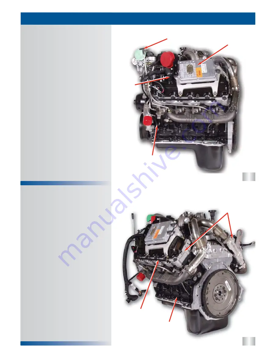
1) Rocker Arm Carrier

2) Bed Plate

3) Glow Plug Buss Bar

1) FICM

2) CMP Sensor

3) Oil Level Gauge

4) Crankcase Ventilation

Left Rear of Engine

Left of Engine

C O M P O N E N T   L O C A T I O N S

10

1

3

2

1

3

4

2

Summary of Contents for 6.0L POWER STROKE

Page 1: ... F Series Super Duty ...

Page 2: ... you should follow when you work on a vehicle Always wear safety glasses for eye protection Use safety stands whenever a procedure requires you to be under the vehicle Be sure that the ignition switch is always in the OFF position unless otherwise required by the procedure Never perform any service to the engine with the air cleaner removed and the engine running unless a turbocharger compressor i...

Page 3: ...This page intentionally left blank ...

Page 4: ...p 19 LUBRICATION SYSTEM 21 System Flow 21 FUEL SUPPLY SYSTEM 27 System Flow 27 Check Valve 30 AIR MANAGEMENT SYSTEM 31 System Flow 31 VGT 34 EGR 37 FUEL MANAGEMENT SYSTEM 39 High Pressure Oil System 40 System Flow 40 Fuel Injectors 43 Stages of Injection 45 ELECTRICAL COMPONENTS 49 Sensors 49 Actuators 64 Other Electrical Components 65 UNIQUE SERVICE PROCEDURES 69 GENERAL DIAGNOSTICS 79 APPENDIX 8...

Page 5: ...This page intentionally left blank ...

Page 6: ...1 Direct Injection Turbocharged Diesel Engine 6 0L Power Stroke ...

Page 7: ...ications Physical ID Labeling 2 Engine Features Variable Geometry Turbocharger Digital Fuel Injection 4 Valves per Cylinder Reusable Gaskets Rear Gear train Dual Timing System 3 6 The 6 0L Power Stroke has been designed to meet the customers expectations of high horsepower and torque over a wide RPM range The 6 0L Power Stroke has also been designed to meet the tougher emissions standards set by t...

Page 8: ...o with oil 966 lb 438 kg Coolant Flow 74 7 gal min 282 8 L min 3300 RPM Air Flow RPM 732 CFM 20 7 m3 min 3300 RPM Exhaust Flow RPM 1499 CFM 42 4 m3 min 3300 RPM Oil Flow RPM 18 5 gal min 70 L min 3300 RPM Cooling System Capacity engine only 11 1 qts 10 5 L Lube System Capacity including filter 15 qts 14 2 L Firing Order 1 2 7 3 4 5 6 8 2 8 4 6 7 5 3 1 Front L R 5 7 The 6 0L Power Stroke engine is ...

Page 9: ... O K E O V E RV I E W 8 The engine serial number is located on the left rear corner of the crankcase The engine serial number identifies the engine family build location and the sequential build number 6 0 is the engine family identifier HU2U is a manufacturing designator 6000173 is a sequential build number States the horsepower rating for the engine programmed in the powertrain control module PC...

Page 10: ...ndary Fuel Filter 6 EGR Throttle Position Sensor If Equipped 1 Thermostat 2 Fuel Inlets on Cylinder Heads 3 Fuel Pressure Regulator 4 ECT Sensor 5 EGR Throttle Actuator If Equipped Left Front of Engine Front of Engine C O M P O N E N T L O C AT I O N S 9 1 2 2 3 5 4 1 2 3 4 5 6 ...

Page 11: ...12 1 Rocker Arm Carrier 2 Bed Plate 3 Glow Plug Buss Bar 1 FICM 2 CMP Sensor 3 Oil Level Gauge 4 Crankcase Ventilation Left Rear of Engine Left of Engine C O M P O N E N T L O C AT I O N S 10 1 3 2 1 3 4 2 ...

Page 12: ...urbine Outlet 3 Exhaust Connection to EGR Cooler 4 Exhaust Expansion Joint 1 Exhaust Expansion Joints 2 Heat Shields 3 Lifting Eye 4 Serial Number 5 ICP Sensor IPR Behind ICP Rear of Engine C O M P O N E N T L O C AT I O N S 11 1 2 2 3 4 1 3 2 5 4 ...

Page 13: ...15 16 1 Heater Return 2 EGR Throttle Actuator 1 CKP Sensor 2 Glow Plug Control Module Right Front of Engine Right Side of Engine C O M P O N E N T L O C AT I O N S 12 1 2 1 2 ...

Page 14: ...utlet 4 IAT2 Sensor 5 EOP Switch 6 EOT Sensor 1 Oil Filter 2 Turbocharger Oil Supply Line 3 EVRT VGT Control Valve 4 Injector Connectors 5 Secondary Fuel Filter 6 EGR Cooler Coolant Deaeration Port Top of Engine C O M P O N E N T L O C AT I O N S 13 1 6 5 2 3 4 2 3 4 6 5 1 ...

Page 15: ... by the cylinder head bolts The rocker arm carrier provides the mounting location for all of the rocker fulcrums The carrier also provides the connector pass through for the injector and glow plug The 6 0L POWER STROKE uses a four 4 valve per cylinder head design to increase air flow and efficiency For identification the exhaust valves are smaller than the intake valves CONNECTOR PASS THROUGH CONN...

Page 16: ... Stroke uses two different flywheels for the manual transmission A dual mass flywheel is used on the F 250 350 Superduty truck The dual mass flywheel can be identified by springs located around the flywheel on the engine side It can also be identified by an extra ring of bolts on the transmission side of the flywheel that holds the two masses together From the side it can be identified by the sepa...

Page 17: ...16 This page intentionally left blank ...

Page 18: ...or hoses Both the glow plug sleeves and the injector sleeves are stainless steel Cooling System Features C O O L I N G S Y S T E M Cooling System Flow Cooling System Features Modular Water Pump Stainless Steel Injector Sleeves Stainless Steel Glow Plug Sleeves 25 17 26 ...

Page 19: ... in metal one piece gasket and is directed out of the front cover through three 3 passages Two of the passages route coolant to the crankcase to cool the cylinder walls and cylinder heads The third passage routes coolant to the oil cooler via a passage in the crankcase There are two passages for coolant to return from the crankcase into the front cover Coolant is directed out of the crankcase and ...

Page 20: ...e water pump hub and impeller is mounted into the front cover which is the housing for the water pump The water pump impeller pulls coolant from the center of the housing and pushes it outward The water pump has a built in reservoir to catch small amounts coolant that during normal operation of the engine may seep past the seal Note The water pump impeller may be damaged if dropped or hit by a har...

Page 21: ...lant Recovery Bottle Glow Plug Sleeve C O O L I N G S Y S T E M 20 Glow plug sleeves are used to keep coolant from coming in direct contact with the glow plugs and to seal coolant from the combustion chamber The glow plug sleeve is replaceable See unique service procedures or the service manual for more details GLOW PLUG SLEEVE GLOW PLUG SLEEVE COOLANT RECOVERY BOTTLE COOLANT RECOVERY BOTTLE TO EG...

Page 22: ...s reduces the chance for oil leaks The oil filter is a canister style filter mounted on the top of the engine that drains to the oil pan during servicing The gerotor oil pump and oil pressure regulator are both located in the front of the engine behind the vibration damper Lubrication System Features Integrated Oil Cooler No External Oil Passages in Crankcase Easy Access Canister Style Oil Filter ...

Page 23: ...lubrication and VGT control via an external line The oil also is provided to the oil reservoir that supplies the high pressure oil pump The two 2 other passages are to the tappet oil feed on the right and left banks The tappet galleries also provide oil to the piston cooling jets Cross drillings off of the right bank tappet gallery feed the cam bearings then the crankshaft main bearings The cranks...

Page 24: ...The oil pressure regulator is located in the front cover just below the gerotor oil pump The oil pressure regulator is calibrated to open at pressures above 75 psi It should be closed below that pressure The gerotor oil pump is driven off of the flats on the nose of the crankshaft The pump is designed to flow the large volume of oil required for the 6 0L POWER STROKE The gerotor oil pump front cov...

Page 25: ...s damaged it could cause contamination of the lubrication and cooling systems The oil cooler housing has passages in it to direct the flow of coolant and oil Oil is routed from the front of the crankcase to the back of the housing where it enters the oil cooler The oil passes from the rear of the oil cooler to the front of the cooler and is cooled in the process The oil is then sent to the oil fil...

Page 26: ...ed before draining the oil from the oil pan so that the oil can drain from the filter housing into the oil pan The oil filter base routes oil to the oil filter engine oil pressure switch EOP engine oil temperature sensor EOT and the turbocharger oil feed The oil filter base also houses the anti drain back check valve that keeps oil in the oil filter assembly after the engine is shut off The oil co...

Page 27: ...to the oil pan The passage in the bottom of the reservoir is for oil feed to the high pressure oil pump The coolant passage is for coolant feed from the water pump to the oil cooler Oil is supplied to the turbocharger from the oil filter base via a flexible steel braided oil line to the top of the turbocharger The oil line is connected to the oil filter base using a snap to connect fitting and req...

Page 28: ... There is a check valve in the front of each cylinder head that does not allow fuel to return to the fuel supply system This type of system is called a dead end fuel system Fuel Supply System Features F U E L S U P P LY S Y S T E M 52 Engine Fuel System Flow 27 Fuel Supply System Features Horizontal Fuel Conditioning Module HFCM Secondary Fuel Filter Fuel Check Valves 51 FUEL SUPPLY TO HEADS FUEL ...

Page 29: ...lines past the fuel check valves The fuel is directed to the injectors via passages that are drilled into the cylinder heads Once the fuel has entered the head past the check valve it does not return to the fuel supply system This is called a dead end fuel system The fuel pump located in the Horizontal Fuel Conditioning Module HFCM draws fuel from the fuel tank and through a 10 micron fuel filter ...

Page 30: ...uel filter in the HFCM The DTRM starts to open recirculating fuel back into the pump at 80 F 27 C and is fully open at 50 F 10 C The HFCM is mounted to the frame rail on the drivers side The HFCM is a single module that performs multiple tasks It heats fuel separates water from the fuel senses when water is present in the fuel filters particulates from the fuel creates fuel pressure needed to to s...

Page 31: ...his specification Fuel Inlet Check Valves Fuel Pressure Regulator F U E L S U P P LY S Y S T E M 30 Each cylinder head has a fuel inlet check valve at the front of the head The check valve is incorporated into the bolt for the banjo fitting that attaches the fuel line to the head The check valves are used to maintain constant fuel pressure in the fuel rail The fuel lines are sealed to the head by ...

Page 32: ...tem Features A I R M A N A G E M E N T S Y S T E M Air Management System Components Features Air Filter Filter Minder Variable Geometry Turbocharger VGT Charge Air Cooler Intake Manifold EGR System 60 Air management System Flow 31 FROM CHARGE AIR COOLER EGR VALVE COMPRESSOR OUTLET EGR COOLER TURBINE OUTLET COMPRESSOR INLET THROTTLE BODY 61 ...

Page 33: ...e a throttle plate For 2003 25 the throttle plate will not be active in the pcm strategy The intake manifold directs the air to the intake ports of the cylinder heads The burned air fuel mixture is pushed out of the cylinder into the exhaust manifold which collects the exhaust gases and routes them to the turbocharger turbine wheel The exhaust up pipe connected to the passenger side exhaust Air en...

Page 34: ...eplacement The filter element is a honeycomb design The air filter is located on the drivers side of the engine compartment between the battery and the radiator A filter minder device used to measure filter restriction is located on the back of the air filter housing Fresh air from the drivers side fender and the grill area is drawn into the air filter and particulates are removed from the air bef...

Page 35: ...anes of the turbocharger are closed the engine will have a higher exhaust back pressure and create more heat which will in turn warm the engine faster in cold ambient conditions The compressor on the VGT is similar to the compressor on a conventional turbocharger The compressor wheel is connected to the turbine via a common shaft The VGT uses a turbine wheel that is similar to a conventional turbo...

Page 36: ...e VGT COIL OIL DRAIN TO PAN OIL TO CLOSE SIDE OF PISTON OIL SUPPLY OIL TO OPEN SIDE OF PISTON CAM FOLLOWER 70 VGTCV Flows When the VGTCV is commanded to the full open position low or no duty cycle oil from the oil supply line is directed to the open side of the actuator piston Oil on the closed side of the piston is then directed through the actuator piston back to the VGTCV and then to drain Note...

Page 37: ...the correct amount of boost to the engine for optimal combustion as well as providing the necessary back pressure to drive EGR Note The VGT control valve piston is coupled to the vanes through a shaft and the unison ring VGT Turbine Vanes Partially Closed During engine operation at low engine speeds and load little energy is available from the exhaust to generate boost In order to maximize the use...

Page 38: ...ld EGR Cooler EGR Flow EGR Valve A I R M A N A G E M E N T S Y S T E M 37 The PCM controlled EGR Exhaust Gas Recirculation valve adds cooled exhaust gases to the intake manifold to reduce NOx emissions The EGR valve is opened during steady state throttle positions when exhaust back pressures are higher than intake manifold pressures boost The EGR valve has two valves connected by a common shaft Co...

Page 39: ...s to equalize pressure on both sides of the manifold Intake Manifold INTAKE MANIFOLD EGR COOLER 81 NO THROTTLE PLATE 80 THROTTLE PLATE 79 All 2003 25 6 0L Power Stroke engines are equipped with a throttle body Some early versions also have a throttle plate in the throttle body Later versions will retain the throttle body but not the throttle plate The throttle was designed to assist with EGR opera...

Page 40: ...sed of several sub systems Fuel Supply System High Pressure Oil System Lubrication System Sensors Injectors Electrical Components Actuators Generation II Fuel Management System Major Components Generation II Fuel Management System Advantages Emissions and noise have been reduced through improvements in rate and timing control No external high pressure oil lines exist The high pressure system s pre...

Page 41: ...area to the high pressure lines High pressure oil line connects the stand pipes to the high pressure oil rail High pressure oil rail is bolted to the cylinder heads and acts as a reservoir for high pressure oil Check valves incorporated in the inlet fitting for the high pressure oil rail limit hydraulic disturbance feed back from injector operation Injectors deliver fuel when the spool valve is po...

Page 42: ...0 PSI Relief Valve Check Valve with Orifice ICP Sensor 86 41 fastened to the cylinder head and connected to the top of the injectors After lube oil is cooled and filtered some is directed to the reservoir The reservoir provides oil to the high pressure pump The IPR Injection Pressure Regulator is PCM controlled and contains the system s pressure relief valve which opens at 4000 psi The plumbing fr...

Page 43: ...he high pressure oil rail and two specially designed end caps are used The IPR and ICP are both installed into the high pressure pump cover beneath the turbocharger turbine inlet pipes The high pressure pump is installed inside the crankcase The pump is a seven 7 piston swash plate style pump that is driven off of the rear gear train Minor leakage from the pump will not create external oil leaks B...

Page 44: ...injector and one 1 replaceable copper combustion gasket on the tip of the injector The injector s two 2 coils have a single four 4 pin connector that passes through the rocker arm carrier There is an open coil and a close coil on the injector that move the spool valve from side to side using magnetic force The spool valve has two positions when the valve is in the open position it allows oil to fl...

Page 45: ...ol pressure ICP is The bottom of plunger and barrel of the injector is where the fuel injection pressure is built When the plunger is pushed downward by the intensifier piston it increases the fuel pressure in the barrel 7 1 times that of the ICP pressure The plunger is coated with a tungsten carbide coating to reduce the possibility of scuffing and poor performance The injection nozzle needle is ...

Page 46: ...cycle This is called pilot injection During the fill stage the spool valve is in the closed position High pressure oil from the oil rail is dead headed at the spool valve Low pressure fuel fills the port below the plunger The needle control spring holds the needle on its seat so that fuel can not enter the combustion chamber Three Stages of Injection Fill Main Injection End of Main Injection 96 SP...

Page 47: ...arts to build once the plunger passes the fuel spill port of the barrel Force on the nozzle needle begins to build The pulse width controlled current is shut off after 800 µsec micro second or millionth of a second but the spool remains in the open position High pressure oil from the rail continues to flow past the spool valve The intensifier piston and plunger continue to move and pressure increa...

Page 48: ...lve to the closed position High pressure oil is dead headed against the spool valve The pulse width controlled current is shut off after 800 µsec micro seconds or millionth of a second but the spool remains in the closed position The intensifier piston and plunger begin to return to their initial position Oil above the intensifier piston flows past the spool valve through the exhaust ports Fuel pr...

Page 49: ...48 This page intentionally left blank ...

Page 50: ...ds a Vref of 5 0 volts to the engine sensors except for CMP and CKP which generate voltage through the collapse of a magnetic field The PCM uses 5 volts as the reference voltage to maintain consistency throughout all operating conditions The Vref is conditioned by the sensors then returned to the PCM for use in determining the fueling strategy Sensors Overview Electrical Components Sensors Actuato...

Page 51: ...the movement of the AP if one of the three potentiometer readings do not agree the check engine light will illuminate and the vehicle will continue to perform as normal If two signals from the AP are lost the PCM will allow the engine to idle only and illuminate the check engine light The three track pedal is a safety feature The three track pedal takes the place of the Idle Validation Switch allo...

Page 52: ...ble capacitance sensor The PCM supplies a 5 volt reference signal which the BP sensor uses to produce a linear analog voltage signal that indicates pressure The primary function of the BP sensor is to provide altitude information so that the PCM can adjust timing fuel quantity glow plug on time and VGT control ...

Page 53: ...ld created by the permanent magnet that is in the 106 creates a signal the relates to crankshaft speed and position relative to TDC Top Dead Center The CMP creates a signal relative to which stroke the piston is currently on compression or exhaust end of the sensor Crankshaft speed is derived from the frequency of the CKP sensor signal Crankshaft position can be determined by the sycronization of ...

Page 54: ...at the FICM can perform fueling calculations The PCM conditions the signal and sends it out as TACH signal for body builder use Diagnostic information on the CMP input signal is obtained by performing accuracy checks on signal levels frequency and or duty cycle with software strategies The ECM needs both the CKP and CMP signal to calculate engine speed and position The CMP creates a signal that th...

Page 55: ...ignal voltage decreases The ECT sensor is a two 2 wire thermistor sensor The PCM supplies a 5 volt reference signal which the ECT sensor uses to produce an analog voltage The ECT sensor changes resistance when exposed to different temperatures When the temperature of the coolant decreases the resistance of the thermistor increases and the signal voltage increases 54 ...

Page 56: ...ensor The PCM supplies a 5 volt reference voltage that the EGRVP uses to produce a linear analog voltage that indicates the amount of movement of the valve The PCM monitors EGRP as the engine is operating to modulate the EGR valve This is a closed loop function which means that the PCM continuously monitors the EGRVP to ensure proper valve operation ...

Page 57: ...und after engine oil pressure reaches approximately 5 7psi This switch controls the oil pressure gauge on the instrument panel When pressure is above 7psi the gauge will read normal and if the pressure drops below 6 psi the gauge will show 0 The information from the switch is not fed back to the PCM in any way and is to be used as a reference only 56 ...

Page 58: ...log voltage that indicates temperature The PCM monitors engine oil temperature via the EOT sensor signal to control EGR glow plugs VGT and fuel quantity and timing throughout the operating range of the engine The EOT signal allows the PCM to compensate for oil viscosity variations due to temperature changes in the operating environment ensuring adequate power and torque are available for all opera...

Page 59: ... sensor is a three 3 wire variable capacitance sensor The PCM supplies a 5 volt reference signal which the EP sensor uses to produce a linear analog voltage that indicates pressure The EP measures exhaust back pressure so that the PCM can control the VGT and EGR system 58 ...

Page 60: ...e PCM supplies a 5 volt reference signal which the IAT1 uses to produce an analog voltage that indicates the intake air temperature The IAT1 sensor s primary function is to measure intake air temperature to control the timing and fuel rate when cold starting The continuous monitoring by the IAT1 sensor limits smoke emis sions The MAF IAT1 sensor is mounted in the intake air piping after the air fi...

Page 61: ...tisfactory During engine operation if the PCM recognizes that the IAT2 signal is lower or higher than the expected value it will set a Diagnostic Trouble Code DTC and illuminate the amber malfunction indicator lamp on the dash The IAT2 sensor is a two 2 wire thermistor type sensor The IAT2 sensor changes resistance when exposed to different air temperature When temperature decreases the resistance...

Page 62: ... set a Diagnostic Trouble Code DTC and illuminate the amber malfunction indicator lamp on the dash The ICP signal from the PCM is one of the signals the FICM uses to command the correct injection timing The ICP sensor is a three 3 wire variable capacitance sensor The PCM supplies a 5 volt reference signal which the ICP sensor uses to produce a linear analog voltage that indicates pressure The prim...

Page 63: ...he engine Air passing over the hot wire causes it to cool This hot wire is maintained at 200 C 392 F above ambient temperature as measured by a constant cold wire The current required to maintain the temperature of the hot wire is proportional to the air mass flow The MAF sensor then outputs and analog voltage signal to the PCM proportional to the air mass 116 ...

Page 64: ...A L C O M P O N E N T S 63 117 The MAP sensor is a three 3 wire variable capacitance sensor The PCM uses the MAP sensor signal to assist in the calculation of EGR duty cycle The PCM measures the MAP signal to determine intake manifold boost pressure ...

Page 65: ...the valve is disconnected it is in its open or drain state and the engine should not start The IPR valve also contains the pressure relief valve for the high pressure oil system Actuators convert electrical output from the PCM to hydraulic mechanical or electronic work The 6 0L Power Stroke uses four 4 actuators Injection Pressure Regulator Exhaust Gas Recirculation Valve Variable Geometry Turboch...

Page 66: ...Variable Geometry Turbocharger Control Valve E L E C T R I C A L C O M P O N E N T S 65 The FICM Fuel Injection Control Module receives Information from the PCM like volume of fuel desired RPM EOT ICP and others and uses those signals to calculate injector start of injection and duration After calculating injector fuel delivery time the IDM sends a 48 volt 20 amp pulse to the correct injector so t...

Page 67: ...hort is detected in that circuit The glow plug system is used to warm the air in the cylinders to enhance cold weather startability and reduce start up smoke The glow plug system is PCM controlled The Powertrain Control Module PCM which is mounted behind the battery on the drivers side inner fender panel uses sensor inputs to control actuators and send fueling commands to the FICM The PCM controls...

Page 68: ...he glow plugs on that bank Glow Plug Buss Bar Glow Plug Sleeve Glow Plug E L E C T R I C A L C O M P O N E N T S 67 The glow plug is used to heat the air in the cylinder Inside the plug are two 2 coils resistance connected in series one to create heat and one to control heat at its peak The glow plug sleeve is used to protect the glow plug from engine coolant and is made of stainless steel GLOW PL...

Page 69: ...system into a cold condition for about 40 sec the glow plug amperage should be stable Each glow plug should draw between 10 12 amps When testing the glow plug system it is best to measure one bank of glow plugs at a time The bank with the lower current draw would be the bank with the bad glow plug and or wiring concerns E L E C T R I C A L C O M P O N E N T S 68 Glow Plug System Diagnostics GLOW P...

Page 70: ...ankcase Drain the oil from the oil pan After all of the oil has drained from the oil pan remove the oil filter and discard it in the appropriate location Note The oil filter snaps into the oil filter lid Install the new oil filter element and tighten the oil filter cap to the recommended torque This will close the oil filter drain Refill crankcase with correct volume of recommended oil After remov...

Page 71: ...e this will also unseat the injector from it s bore Note Do not use air tools to remove the injector Carefully lift the injector from the bore Note Do not pry on the injector coils to remove the injector they may be damaged and are not replaceable Also watch for rocker arm to injector interference Note Make sure that the copper gasket at the bottom of the injector has not fallen into the injector ...

Page 72: ...wn on the injector Note Make sure that the copper washer does not fall off the tip of the injector during installation engine damage could result if the gasket is not in place Using the hold down bolt to seat the injector in the bore slowly tighten the bolt to the specified torque Note Again do not use air electric tools to install injectors Before installing the high pressure oil rail to the rock...

Page 73: ...reassembly Note If the rocker arms and or valve bridges are not correctly installed premature valve train wear may result To remove the rocker arm fulcrums first remove the corresponding head bolt and then the small fulcrum retaining bolt Note If one or more of the cylinder head bolts are removed required for rocker arm carrier replacement then the cylinder head gasket and all cylinder head bolts ...

Page 74: ...mbined First clean out any sealant from the bore before installing a new sleeve Apply sealant Loctite 620 green in color to the two 2 locations that the sleeve contacts the cylinder head Note Refer to service manual for proper location of sealant application Use the special tool tool 303 767 for injector sleeve or tool 303 763 for glow plug sleeve to drive the sleeve into its bore To remove the EG...

Page 75: ...e tool 303 755 to remove the oil feed to the turbocharger that is connected to the oil filter base The connection at the turbocharger is a bolted flange and is sealed with a gasket 74 To disconnect the crankcase ventilation tube from the engine remove the air inlet tube from the compressor inlet and rotate the vent counter clockwise until it releases Note Since the 6 0L POWER STROKE uses a closed ...

Page 76: ...urbocharger oil drain is located under the turbocharger and is sealed with o rings To remove the drain tube pull it forward out of the high pressure pump cover When reinstalling the intake manifold the locating tabs on the intake manifold gasket should face up and toward the center of the engine There is a port on the intake manifold for cooling system deaeration that returns to the coolant reserv...

Page 77: ...e discharge tube o ring before installing the cover The point were the crankcase and main bearing carrier meet is sealed to the front cover gasket with a dab of RTV sealant that must be cut to remove the front cover gasket The front cover is located to the crankcase with dowels Note If the dowels are missing or damaged the front cover could be misaligned and damage to the cover or oil pump could r...

Page 78: ... Gerotor Oil Pump U N I Q U E S E RV I C E P R O C E D U R E S When installing the front cover the joint between the crankcase and main bearing carrier needs a dab of RTV sealer applied Note If too much sealant is applied it could get into the lube oil system The lube oil pump is located to the front cover by dowels and sealed with a push in place gasket 155 77 PRESS IN PLACE GASKET PRESS IN PLACE...

Page 79: ...al damage will occur There is a metal plate pressed onto the primary flange of the crankshaft This plate acts as a dust shield for the rear seal and the mounting surface for the flexplate flywheel The plate must be removed before the rear cover can be removed It can be removed with a common finger type gear puller Crankshaft Primary Flange Crankshaft Rear Seal Dust Cover U N I Q U E S E RV I C E P...

Page 80: ... pump module from the fuel pump module Install a 1 4 ID hose to the fuel pump module and place the other end of the hose into a diesel fuel safe container Turn the ignition to the on position The fuel pump will run for approx 20 sec Continue to cycle the key to the on position until fuel flows from the attached hose Start the engine run at WOT and observe the returning fuel for air If air is prese...

Page 81: ...er of the engine compartment If you have no 0 psi ICP pressure during crank it could be the result of major high pressure oil leak lack of oil supply to the high pressure pump bad high pressure pump or the gear on the high pressure pump is loose Use PC ED ICP diagnostics to determine root cause If ICP during crank is between 200 300 psi and does not change as IPR duty cycle increases the IPR valve...

Page 82: ...M during each compression stroke while cranking the engine It then compares the RPM of all of the cylinders to determine if there is a cylinder that is weaker than the rest Once a cylinder is determined to be weak a manual compression test should be run on that cylinder and a good cylinder to verify results The cylinder balance test is now available for the 6 0L Power Stroke The cylinder balance t...

Page 83: ...wer feed to the FICM To check powers and grounds to the FICM you can bring up the following pids on the WDS FICMVPWR FICM Vehicle Power battery voltage FICMMPWR FICM Main Power or output voltage approximately 48 volts FICMLPWR FICM Logic Power battery voltage A new crankcase pressure orifice tool has been developed for the 6 0L Power Stroke The new tool has a smaller orifice in the top so that mor...

Page 84: ...A P P E N D I X 83 TABLE OF CONTENTS Torque Charts 84 Hard Start No Start Diagnostics 88 Performance Diagnostics 89 Wiring Diagrams 90 Diagnostic Codes 94 Glossary 97 Index 100 Notes 103 ...

Page 85: ...bf ft 27 Nm Exhaust up pipe coupling on right side 20 lbf ft 27 Nm Flywheel bolts see figure B 69 lbf ft 94 Nm Front cover module bolts 18 lbf ft 24 Nm Fuel check valve banjo bolt 28 lbf ft 38 Nm Fuel filter supply and return lines 32 lbf ft 43 Nm Fuel filter supply to head lines 19 lbf ft 26 Nm Fuel injector hold down 24 lbf ft 33 Nm Fuel rail plug rear of head 20 lbf ft 27 Nm Glow plug 14 lbf ft...

Page 86: ...ounting bracket bolts see note 2 28 lbf ft 38 Nm Turbo bracket to crankcase mounting bolts 23 lbf ft 31 Nm Valve cover bolts 71 lbf in 8 Nm Vibration damper see note 5 initial 50 lbf ft 68 Nm Final additional 90 degrees rotation COMPONENT STANDARD METRIC STANDARD TORQUE CHART Hex Flange Head Thread Torque Torque Wrench Diameter lbf ft Nm Size mm M6 x 1 8 11 8 M8 x 1 25 18 24 10 M10 x 1 5 36 49 13 ...

Page 87: ...he numerical sequence shown Step 5 Tighten the M14 cylinder head bolts an additional 90o clockwise in the numerical sequence shown Step 6 Torque the M8 11 15 cylinder head bolts to 18 lbf ft 24 Nm in the numerical sequence shown Final Step Torque the M8 cylinder head bolts to 24 lbf ft 32 Nm in the numerical sequence shown Note Always use new head bolts 5 9 8 4 2 6 7 3 1 10 15 14 12 11 13 Intake S...

Page 88: ...ld Bolts Step 1 Install bolts 1 through 8 finger tight Step 2 Torque bolts 9 though 16 to 8 lbf ft 11 Nm Final step Torque all bolts to 8 lbf ft 11 Nm in the numerical sequence shown Front of Engine 12 11 10 9 4 20 19 1 7 2 3 5 6 17 18 8 16 15 14 13 Bottom View Figure E Main Bearing Bolts Step 1 Torque the bolts to 110 lbf ft 149 Nm in the numerical sequence shown Step 2 Torque the bolts to 130 lb...

Page 89: ...easure each Glow Plug resistance to Bat ground Visual Parameter Spec Measurement Measure engine harness resistance to GPCM V PWR Glow Glow Plug Harness to 4 Sufficient Clean Fuel FICMLPWR 8 volt min Plug to Ground GPCM connector Check if the WATER IN FUEL lamp has been FICMVPWR Number 1 to 2 ohms 0 to 1 ohms illuminated RPM 100 RPM 1 After verifying that there is fuel in the tank drain a minimum 3...

Page 90: ...00 RPM Perform boost test at 3300 RPM Visual 10a Electric Fuel Pump Pressure Monitor MGP and RPM with scan tool Measure fuel pressure at engine filter housing test port Road Test select appropriate gear to obtain desired engine 4 Perform KOEO On Demand Test Road Test engine at full load condition speed and full load on engine climbing hill or loaded truck Use the scan tool Instrument Spec Measurem...

Page 91: ...W I R I N G D I A G R A M S I N G L E A LT 90 ...

Page 92: ...W I R I N G D I A G R A M S I N G L E A LT 91 ...

Page 93: ...W I R I N G D I A G R A M D U A L A LT 92 ...

Page 94: ...W I R I N G D I A G R A M D U A L A LT 93 ...

Page 95: ...f a change in EOT and MFDES Faulty Biased sensor circuit fault PCM P0197 C O R Engine Oil Temperature Sensor Circuit Low Input Checks EOT for a temperature higher than a specified oil temperature expected for normal operations WHEN eot VOLTAGE IS LESS THAN 0 15 VOLTS Default 212o F 100o C no fast idle Shorted to ground on the circuit P0198 C O R Engine Oil Temperature Sensor Circuit High Input Che...

Page 96: ...cuit malfunction Cruise control code will be set on every switch test on vevicles not equipped with cruise control P0602 C O R Powertrain Control Module Programming Error P0603 C Powertrain Control Module Keep Alive Memory KAM Error No historical faults output during self test Disconnected Discharged Battery Open PCM pin faulty PCM P0605 O Powertrain Control Module Read Only Memory ROM Error PCM f...

Page 97: ... No boost pressure increase was detected MAP hose MAP sensor CAC system leaks Intake leaks EP sensor exhaust restriction P2263 C Turbo Super Charger System Performance MAP hose MAP sensor CAC system leaks Intake leaks EP sensor exhaust restriction exhaust leaks P2269 C O R Water in Fuel Condition Indicates water in fuel Drain water in fuel seperator defective WIF sensor circuit integrity P2284 C R...

Page 98: ...l pump and power steering pump that are made into one unit and driven off of the rear gear train Digital Fuel Injection A fuel injection system that uses both an open and close signal to control fuel injectors Dual Timing System A timing System that uses both a CKP and CMP sensors to determine engine speed and rotational position DVOM Digital Volt Ohm Meter A meter that uses a digital display to i...

Page 99: ...ol Coolant A premium coolant with an Ethylene Glycol base that can be used in a cooling system for an extended time without need ing to be changed Long life coolants do not require the use of extenders Long life coolants can be identified by its yellow color Main Power Relays Two Battery power relay switches for the ECM and IDM modules that are key power initiated and controlled by the correspondi...

Page 100: ... Sensor A sensor that is used to determine pressure A variable capacitance sensor changes it capacitance value in relation pressure change Increasing pressure results in a lower capacitance thus increasing return voltage Decreasing pressure results in a higher capacitance and a lower voltage Variable capacitance sensors are 3 wire sensors VBAT Battery voltage VGT Variable Geometry Turbocharger Cou...

Page 101: ...filter replacement 69 Fuel injector 43 Coil 47 End of main injection 47 Features 43 Fill cycle 45 Main injection 46 O rings 43 Spool valve 43 A Actuators 64 Air filter filter minder 33 Air in fuel 79 Air management system features 31 flow 31 32 AP Accelerator Pedal 50 B BP Barometric Pressure 51 Barrel 44 bed plate 22 Bridges 72 C Charge air cooler 33 CKP Crankshaft Position 52 CMP Camshaft Positi...

Page 102: ...Intake Air Temperature 1 59 IAT2 Intake Air Temperature 2 60 ICP Injection Control Pressure 42 61 low 80 Injection nozzle 44 Injector Buzz 82 I O test 80 Installation 71 O ring replacement 70 71 Removal 69 70 Sleeve 19 Installation 73 Removal 73 Intake manifold 38 75 Intensifier Piston 44 IPR Injection Pressure Regulator 42 64 Valve removal 75 L Lubrication system Features 21 flow 21 22 M MAF Mass...

Page 103: ...ywheel 15 Specifications 7 Stages of injection 45 T Table of contents 3 Turbocharger Oil drain tube 26 Removal 75 Oil supply 26 Removal 74 V VGT Variable Geometry Turbocharger Compressor 34 Control valve 35 Flow 35 Features 34 Turbine 34 Vanes closed 36 Vanes open 34 Vanes partially closed 36 VGTCV Variable Geometry Turbocharger Control Valve 65 W Water pump 19 ...

Page 104: ...N O T E S 103 ...

Page 105: ...N O T E S 104 ...

Page 106: ...2002 International Truck and Engine Corporation Printed in the U S A ...

Reviews: