4
OPERATION
Maintenance
• We recommend that the heater is
inspected in Ford authorized workshops
in the start of each winter season.
• Keep the heater air inlet and outlet
ducts clean. Dirty air ducts cause
overheating and deactivation of the
heater control unit.
• Operate the heater once every month
for 10 minutes to prevent the jamming
of the mechanical components.
Error code display
If the heater has a combined timer, an error
code shall be displayed on the screen of the
timer when an error occurs.
Note:
Error code is displayed by the flashing
of the on/off indicator/error code indicator
when an error occurs if the heater has a
control element. After it is flashed rapidly for 5
seconds, error code is displayed by a series
of long flashes, number of flashes is shown
in the table below (e.g. F04 – 4 long flashing
signals).
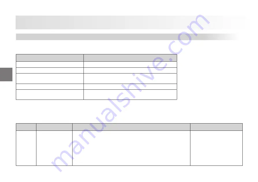
Heater Turns Off By Itself
Malfunction Description
Precaution
No ignition during starting.
Turn off/on the heater once
Flame extinguishes during operation
Turn off/on the heater once
Heater is overheated and green light is
blinking
Turn off/on the heater after cooling it down after checking
whether the air channels are blocked or not
Vehicle voltage is insufficient
Check the battery. Turn off/on the heater once
There's a blockage in air inlet and/or
outlet ducts
Checked whether there's a blockage in air inlet and/or
outlet ducts
Error code
Error (group)
Additional information during computerized diagnosis
Remedy
F 00
Control unit error
01 Control Unit error 81 EOL checksum error
11 Wrong coded control unit or wrong type of heater (fuel type) is installed
(heater does not operate when this error occurs)
91 Neutrally coded or deactivated control unit (heater does not operate
when this error occurs)
92 Resume command fails (heater does not operate when this error oc-
curs)
18 Customer bus is faulty
Replace the control unit
A/C and Heater
101
Summary of Contents for Cargo 2017
Page 1: ...IRUGWUXFNV FRP WU IDFHERRN FRP RUG DUJR 25 5 2 2 1 56 0 18...
Page 5: ...3 1 INTRODUCTION 3...
Page 8: ...1 INTRODUCTION Dashboard 6...
Page 10: ...Safety 2 8...
Page 19: ...3 CONTROLS AND INDICATORS 17...
Page 38: ...CONTROLS AND INDICATORS 3 36...
Page 66: ...CONTROLS AND INDICATORS 3 Tachograph simulator unit 64...
Page 67: ...OPERATION 4 65...
Page 80: ...4 OPERATION Seats and Beds 78...
Page 166: ...MAINTENANCE AND SERVICE 5 164...
Page 228: ...6 TECHNICAL SPECIFICATIONS 226...


