background image


FAT-0113 

EN


Copyright © 2015 

P a g e

 | 

7


www.Ford-tools.com 


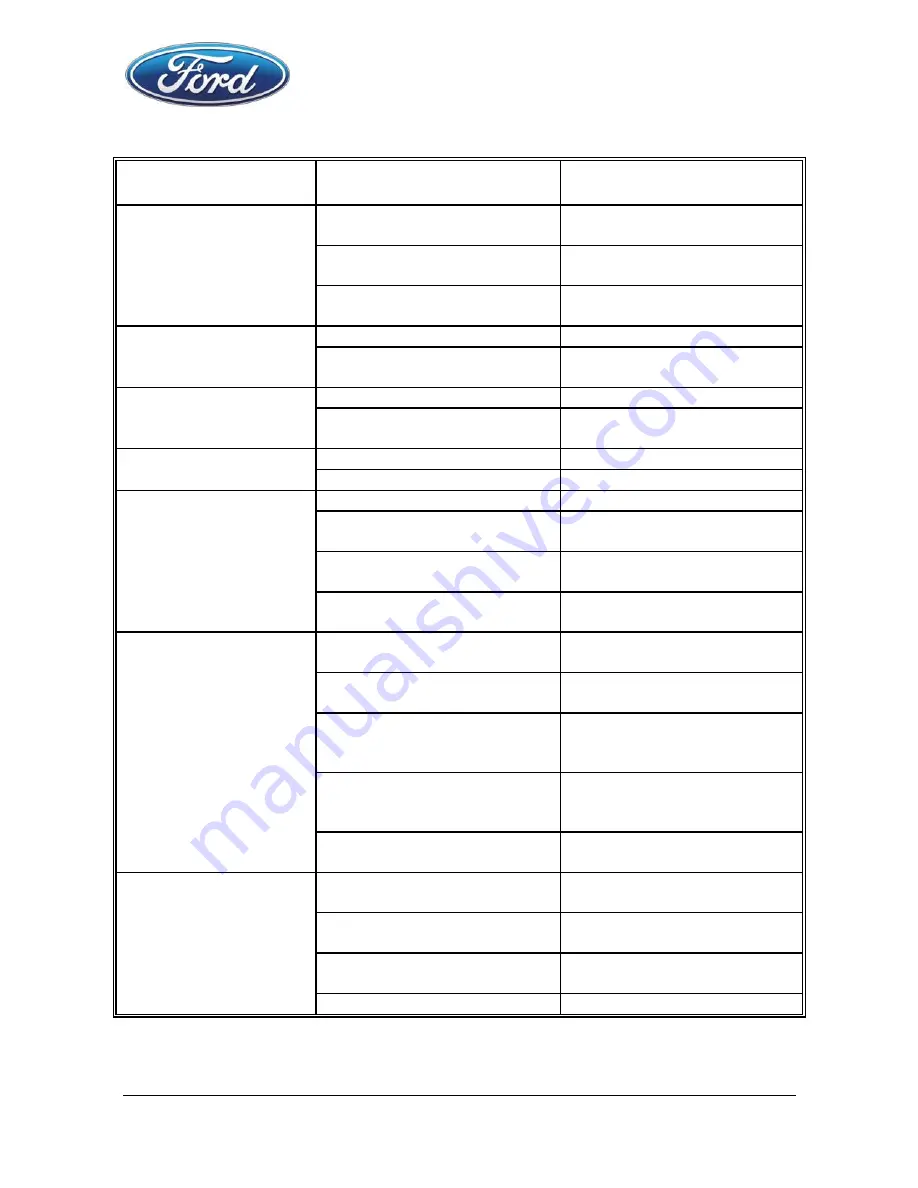
SYMPTOM 

PROBLEM 

SOLUTIONS 

Air leak near top of 

tool or in trigger area 

O-ring in trigger valve is 

damaged. 

Check and replace O-ring. 

Trigger valve head are 

damage. 

Check and replace. 

Trigger valve stem, seal or 

O-ring are damaged. 

Check and replace trigger 

valve stem, seal or O-ring 

Air leak near bottom 

of tool. 

Loose screws. 

Tighten screws. 

Worn or damaged O-rings 

or bumper. 

Check and replace O-rings 

or bumper. 

Air leak between body 

and cylinder cap. 

Loose screws. 

Tighten screw. 

Worn or damaged O-rings 

or seals. 

Check and replace O-rings 

or bumper. 

Blade driving fastener 

too deep. 

Worn bumper. 

Replace bumper. 

Air pressure is too high. 

Adjust the air pressure. 

Tool does not operate 

well: can not drive 

fastener or operate 

sluggishly. 

Inadequate air supply. 

Verify adequate air supply. 

Inadequate lubrication. 

Place 2 or 6 drops of oil 

into air inlet. 

Worn or damaged O-rings 

or seals. 

Check and replace O-rings 

or seal. 

Exhaust port in cylinder 

head is blocked. 

Replace damaged internal 

parts. 

Tool skips fasteners. 

Worn bumper or damaged 

spring. 

Replace bumper or pusher 

spring. 

Dirt in front plate. 

Clean drive channel on 

front plate. 

Dirt or damage prevents 

fasteners from moving 

freely in magazine. 

Magazine needs to be 

cleaned. 

Worn or dry O-ring on 

piston or lack of 

Lubrication. 

O-ring needs to be 

replaced and lubricate. 

Cylinder covers seal 
leaking. 

Replace Sealing washer. 

Tool jams. 

Incorrect or damaged 

fasteners. 

Change and use correct 

fastener. 

Damaged or worn driver 

guide. 

Check and replace the 

driver. 

Magazine or nose screw 

loose. 

Tighten the magazine. 

Magazine is dirty. 

Clean the magazine. 


Summary of Contents for FAT-0113

Page 1: ...L NL NEDERLANDS VERTAALDE VERSIE VAN DE ORIGINELE HANDLEIDING Operation manual and security instructions inside the box Use safety glasses Keep this tool away from children Ford Motor Company trademar...

Page 2: ...2 DESCRIPTION FIG A 2 3 PACKAGE CONTENT LIST 2 4 IMPORTANT SAFETY RULES 3 5 FEATURES 4 5 1 Air supply 4 6 OPERATING INSTRUCTIONS 5 6 1 Loading fastener and operation 5 7 MAINTENANCE 5 8 TECHNICAL DAT...

Page 3: ...er 3 PACKAGE CONTENT LIST Remove all packing materials Remove remaining packaging and transit supports if existing Check the completeness of the packing content Check the appliance and all accessories...

Page 4: ...firing of fastener 7 KEEP THE TOOL POINTED AWAY FROM YOURSELF and others at all time and keep hands any body parts away rear area to Safety guard against possible injury 8 DISCONNECT TOOL FROM AIR SUP...

Page 5: ...5 1 Air supply Use clean Dry and Regulated compressed air at 4 7 bar 60 100psi Never exceed maximum and minimum pressure Too low or too high pressure would cause noise fast worn or misfiring When conn...

Page 6: ...e fastener driving Never operate tool unless safety stand is in contact with workpiece 7 The driven depth of the fastener can be changed by turning adjustment nut in either direction 7 MAINTENANCE WAR...

Page 7: ...I Air inlet 1 4 N P T Dimension 75 275 205mm Weight 1 1kg 9 TROUBLESHOOTING WARNING If any of the following symptoms appears during your operating stop using the tool immediately or serious personal i...

Page 8: ...s not operate well can not drive fastener or operate sluggishly Inadequate air supply Verify adequate air supply Inadequate lubrication Place 2 or 6 drops of oil into air inlet Worn or damaged O rings...

Page 9: ...conformity with the essential requirements and other relevant provisions of the applicable European Directives based on the application of European harmonized standards Any unauthorized modification...

Reviews: