B - 6
ForeRunner
ATM Switch Network Configuration Manual
Configuring Circuit Emulation Services
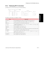
To display the advanced settings of the current CES connections, enter the following:
myswitch::configuration ces> show advanced
Service Clock Partial Max Integ.
Service MapVPI MapVCI Type Mode Cas Fill BufSize CDVT Period
2024 0 129 structured synch basic 0 256 900 2500
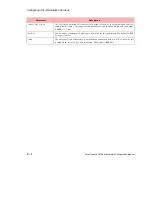
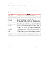
The fields in this display are defined as follows
:
Field
Description
CES Service
The identification number (assigned by the switch) of this CES connection.
MapVPI
The incoming VPI value of the connection.
MapVCI
The incoming VCI value of the connection.
Service Type
Shows if this connection uses structured or unstructured service.
Clock Mode
Synch
means that the connection is in synchronous mode (either structured or unstruc-
tured).
SRTS
means that the connection is in asynchronous (unstructured) mode. (Syn-
chronous Residual Time Stamp (SRTS) clock recovery is enabled on this connection.)
Cas
basic
indicates that Channel Associated Signalling (CAS) will not be used,
cas
indicates
that CAS will be used.
Partial Fill
Indicates how many of the available 47 payload bytes in each cell are used before they are
deemed “full” and ready for transmission across the ATM network (i.e., how much of the
ATM cell contains data and how much is filler). The range for this parameter is 5 to 47. The
default value is 47, for 47 bytes of data. partialfill is used to minimize network transmis-
sion latency and is useful especially with time-sensitive, robbed-bit signalling sources.
Max BufSize
The amount of reassembly buffer space allocated for the connection. The default is 512
bytes per timeslot.
CDVT
The Cell Delay Variation Tolerance for cells being received by the segmentation and reas-
sembly (SAR) engine. The range for this parameter is 100 to 24000 (in
µ
s), and the default
is 2000 (i.e., 2 ms).
Integ. Period
The amount of time allocated to re-establish the connection before, while, or after the call
is established, or in the case of interruption. The default is 2500
µ
s.
Summary of Contents for forerunner series
Page 6: ......
Page 16: ...TOC 10 ForeRunner ATM Switch Network Configuration Manual Table of Contents ...
Page 20: ...LOF 4 ForeRunner ATM Switch Network Configuration Manual List of Figures ...
Page 22: ...LOT 2 ForeRunner ATM Switch Network Configuration Manual List of Tables ...
Page 30: ...viii ForeRunner ATM Switch Network Configuration Manual Preface ...
Page 144: ...3 58 ForeRunner ATM Switch Network Configuration Manual Configuring an Emulated LAN ...
Page 180: ...6 12 ForeRunner ATM Switch Network Configuration Manual ATM Forum PNNI ...
Page 220: ...9 6 ForeRunner ATM Switch Network Configuration Manual Configuring Timing ...
Page 300: ...D 24 ForeRunner ATM Switch Network Configuration Manual Configuring FramePlus Modules ...
Page 308: ...Acronyms 8 ForeRunner ATM Switch Network Configuration Manual Acronyms ...
Page 346: ...Glossary 38 ForeRunner ATM Switch Network Configuration Manual Glossary ...
Page 352: ...Index 6 ForeRunner ATM Switch Network Configuration Manual Index ...

