C - 2
ForeRunner
ATM Switch Network Configuration Manual
Converting from FT-PNNI to PNNI
C.1 ASX-1000 Routing Configuration Issues
This section discusses routing in hierarchical networks in which there are ASX-1000 switches
present in your network. Because each one of the four fabrics appears as a single node in rout-
ing and because you cannot take a two-hop path to go from one switch fabric to another
switch fabric in the same ASX-1000, there are certain FT-PNNI and PNNI node configurations
that should be avoided. These special configurations are addressed individually and alternate
configurations are suggested.
C.1.1 ASX-1000s in FT-PNNI Peer Groups
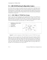
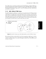
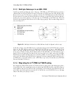
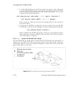
Figure C.1 shows an invalid configuration of an ASX-1000 divided between two FT-PNNI peer
groups called A and B. The ASX-1000’s four FT-PNNI nodes are A.1 and A.2 in peer group A
and B.1 and B.2 in peer group B. From peer group A, the intra-peer group links of peer group
B are not visible. So, the link B.1 to B.2 is not visible in peer group A. Similarly, non-border
nodes B.3 and B.4 belonging to peer group B are not visible in peer group A.
Figure C.1 -
Invalid Configuration of ASX-1000 Split between Two FT-PNNI Peer Groups
Suppose you want to route from A.4 to B.3. After the initial step of prefix matching, the Peer
Group Summary Node (PGSN) of peer group B (not shown in the figure) is chosen as the des-
tination for this path computation. Since B.1 and B.2 both advertise links to the PGSN and
they are equidistant from A.4, A.4 may decide to construct the Destination Transit List (DTL)
as A.4 to A.2 to B.2 to B’s PGSN. When the setup of this call proceeds into peer group B and
reaches node B.2, the only way to route to B.3 is through B.1. But since you cannot take a two-
hop path across the ASX-1000, this call setup will fail.
A.1
A.4
B.1
Backbone link
B.3
B.4
B.2
FT-PNNI node
FT-PNNI peer group boundary
FT-PNNI link
A.3
A.5
A.2
PG A
PG B
Summary of Contents for forerunner series
Page 6: ......
Page 16: ...TOC 10 ForeRunner ATM Switch Network Configuration Manual Table of Contents ...
Page 20: ...LOF 4 ForeRunner ATM Switch Network Configuration Manual List of Figures ...
Page 22: ...LOT 2 ForeRunner ATM Switch Network Configuration Manual List of Tables ...
Page 30: ...viii ForeRunner ATM Switch Network Configuration Manual Preface ...
Page 144: ...3 58 ForeRunner ATM Switch Network Configuration Manual Configuring an Emulated LAN ...
Page 180: ...6 12 ForeRunner ATM Switch Network Configuration Manual ATM Forum PNNI ...
Page 220: ...9 6 ForeRunner ATM Switch Network Configuration Manual Configuring Timing ...
Page 300: ...D 24 ForeRunner ATM Switch Network Configuration Manual Configuring FramePlus Modules ...
Page 308: ...Acronyms 8 ForeRunner ATM Switch Network Configuration Manual Acronyms ...
Page 346: ...Glossary 38 ForeRunner ATM Switch Network Configuration Manual Glossary ...
Page 352: ...Index 6 ForeRunner ATM Switch Network Configuration Manual Index ...

