C - 4
ForeRunner
ATM Switch Network Configuration Manual
Converting from FT-PNNI to PNNI
C.1.3 Multiple Gateways in an ASX-1000
Another potential problem can occur when an ASX-1000 in a FT-PNNI area has gateways
(split-switches with one FT-PNNI and one PNNI node) to a PNNI area. The ASX-1000 can only
have, at most, one of its fabrics as a gateway between the FT-PNNI area and the PNNI area.
This is because if two or more of the fabrics have gateways to the PNNI area, then the link con-
necting any two of the gateways will come up as a PNNI link in the PNNI area. This will
divide up the backplane links between two different peer groups. This invalid configuration is
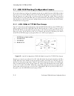
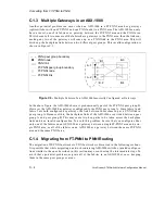
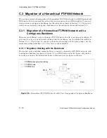
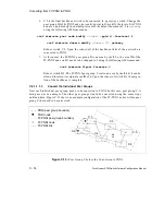
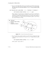
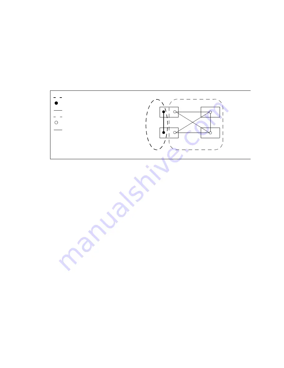
shown in Figure C.3.
Figure C.3 -
Multiple Fabrics of an ASX-1000 Incorrectly Configured as Gateways
In the above figure, the ASX-1000 shown is predominantly part of the FT-PNNI peer group B.
However, the ASX-1000 has gateways configured to the PNNI peer group A. Since fabric 1 and
fabric 2 are both configured as gateways, the link between them comes up as a PNNI link in
peer group A. Because of this, the backplane links of the ASX-1000 are divided between peer
group A and peer group B. This may cause two-hop paths to be taken across the backplane
links and is an invalid configuration. To avoid this problem, be sure that you configure either
only one of the fabrics on an ASX-1000 as a gateway between a single FT-PNNI area and a sin-
gle PNNI area, or all of the fabrics on an ASX-1000 as a gateway between the same FT-PNNI
area and the same PNNI area.
C.1.4 Migrating from FT-PNNI to PNNI Routing
The migration of FT-PNNI networks to PNNI networks is discussed in the following sections.
It is possible that while migrating a network containing ASX-1000 switches, invalid configura-
tions similar to the ones described in this section may occur during the intermediate steps. To
avoid these potential problems, migrate all of the fabrics in an ASX-1000 at once, keeping
them in the same peer groups or areas.
A.1
A.2
B.1
B.3
B.4
B.2
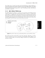
FT-PNNI node
FT-PNNI peer group boundary
FT-PNNI link
PNNI node
PNNI peer group boundary
PNNI link
Summary of Contents for forerunner series
Page 6: ......
Page 16: ...TOC 10 ForeRunner ATM Switch Network Configuration Manual Table of Contents ...
Page 20: ...LOF 4 ForeRunner ATM Switch Network Configuration Manual List of Figures ...
Page 22: ...LOT 2 ForeRunner ATM Switch Network Configuration Manual List of Tables ...
Page 30: ...viii ForeRunner ATM Switch Network Configuration Manual Preface ...
Page 144: ...3 58 ForeRunner ATM Switch Network Configuration Manual Configuring an Emulated LAN ...
Page 180: ...6 12 ForeRunner ATM Switch Network Configuration Manual ATM Forum PNNI ...
Page 220: ...9 6 ForeRunner ATM Switch Network Configuration Manual Configuring Timing ...
Page 300: ...D 24 ForeRunner ATM Switch Network Configuration Manual Configuring FramePlus Modules ...
Page 308: ...Acronyms 8 ForeRunner ATM Switch Network Configuration Manual Acronyms ...
Page 346: ...Glossary 38 ForeRunner ATM Switch Network Configuration Manual Glossary ...
Page 352: ...Index 6 ForeRunner ATM Switch Network Configuration Manual Index ...

