ForeRunner
ATM Switch Network Configuration Manual
1 - 9
Configuring PVCs
Co
nfigu
ri
ng PVCs
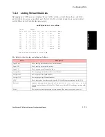
1.3.2 Listing Originating and Terminating Paths
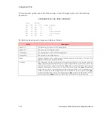
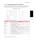
By logging in to AMI, it is possible to display either all of the existing originating and termi-
nating paths on an individual switch fabric or on a specified port. To list all of the originating
and terminating paths on an individual switch fabric, enter the following parameters:
configuration vpt show
Input Output
Port VPI Port VPI ResBW CurBW MinVCI MaxVCI VCs Protocol
1C1 0 terminate N/A 0.8K 1 511 6 pvc
1C1 1 terminate 1.0M 0.8K 1 511 2 pvc
1C2 0 terminate N/A 0.8K 1 511 6 pvc
1C3 0 terminate N/A 0.8K 1 511 6 pvc
1C4 0 terminate N/A 0.8K 1 511 6 pvc
1CTL 0 terminate N/A 7.6K 1 1023 24 pvc
originate 1C1 0 N/A 0.8K 1 511 6 pvc
originate 1C1 1 1.0M 0.8K 1 511 2 pvc
originate 1C2 0 N/A 0.8K 1 511 6 pvc
originate 1C3 0 N/A 0.8K 1 511 6 pvc
originate 1C4 0 N/A 0.8K 1 511 6 pvc
originate 1CTL 0 N/A 7.6K 1 1023 30 pvc
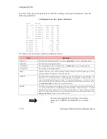
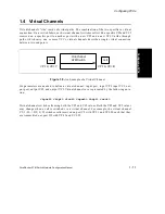
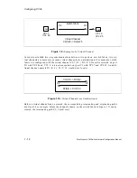
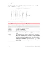
The fields in this display are defined as follows:
Field
Description
Input Port
The incoming port number of the vpt. Shows
originate
if it is an originating path.
Input VPI
The incoming virtual path number.
Output Port
The outgoing port number of the vpt. Shows the number of the output port of the vpt.
Shows
terminate
if it is a terminating path.
Output VPI
The outgoing virtual path number.
ResBW
The maximum amount of bandwidth, in Kbps, that is reserved for the virtual channels
using this vpt. A value of
N/A
indicates that this path is an elastic path. Elastic paths allo-
cate and de-allocate bandwidth for their channels from the link.
CurBW
The amount of bandwidth, in Kbps, being used by the virtual channels using this vpt.
MinVCI
The bottom number for the range of VCIs that are reserved for VCCs on this virtual path
terminator. The default is
1
.
MaxVCI
The top number for the range of VCIs that are reserved for VCCs on this virtual path ter-
minator. The default is
511
.
VCs
The number of virtual channels that are currently using this vpt.
Protocol
The type of protocol running on this channel.
Summary of Contents for forerunner series
Page 6: ......
Page 16: ...TOC 10 ForeRunner ATM Switch Network Configuration Manual Table of Contents ...
Page 20: ...LOF 4 ForeRunner ATM Switch Network Configuration Manual List of Figures ...
Page 22: ...LOT 2 ForeRunner ATM Switch Network Configuration Manual List of Tables ...
Page 30: ...viii ForeRunner ATM Switch Network Configuration Manual Preface ...
Page 144: ...3 58 ForeRunner ATM Switch Network Configuration Manual Configuring an Emulated LAN ...
Page 180: ...6 12 ForeRunner ATM Switch Network Configuration Manual ATM Forum PNNI ...
Page 220: ...9 6 ForeRunner ATM Switch Network Configuration Manual Configuring Timing ...
Page 300: ...D 24 ForeRunner ATM Switch Network Configuration Manual Configuring FramePlus Modules ...
Page 308: ...Acronyms 8 ForeRunner ATM Switch Network Configuration Manual Acronyms ...
Page 346: ...Glossary 38 ForeRunner ATM Switch Network Configuration Manual Glossary ...
Page 352: ...Index 6 ForeRunner ATM Switch Network Configuration Manual Index ...

