ForeRunner
ATM Switch Network Configuration Manual
1 - 19
Configuring PVCs
Co
nfigu
ri
ng PVCs
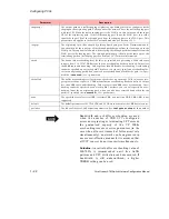
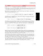
NOTE
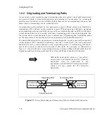
Terminating and originating paths cannot be
created across the intra-fabric ports on an
ASX-1000; only through paths can be created
across the intra-fabric ports as shown in the third
example.
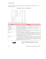
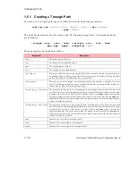
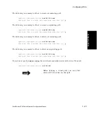
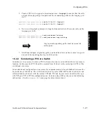
The following is an example of how to create a virtual path which specifies a name:
myswitch::configuration vpc> new 3b1 75 3b5 75 -name customer_b
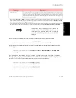
The following is an example of how to create a virtual path which specifies a name and a con-
nection type:
myswitch::configuration vpc> new 3b6 62 3b2 62 -name customer_c -inctype tran
-outctype tran
The following is an example of how to create a virtual path on an ASX-1000. To create a
through path going in port 2A1, VPI 1 on the switch board installed in slot 2 and going out
port 4B1, VPI 1 on the switch board installed in slot 4, enter the following:
myswitch::configuration vpc> new 2a1 1 2e4 1
myswitch::configuration vpc> new 2e4 1 2a1 1
myswitch::configuration vpc> new 4b1 1 4e2 1
myswitch::configuration vpc> new 4e2 1 4b1 1
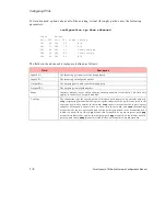
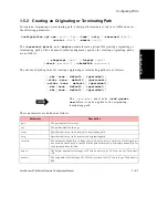
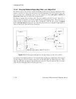
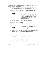
-shapeivpi <vpi>
2
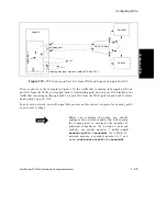
The incoming VPI for this through path. When the traffic shaping port is not the port con-
nected to the WAN, a through path must be created from the WAN port to the traffic shap-
ing port. Cells arrive from the network at the traffic shaping port with this value equal to
the VPI of the terminating path at the traffic shaping port. This parameter only applies to
the Series C network modules.
1.
By indicating
pmp
,
mpp
, or
mpmp
, you are only assigning a label for record keeping purposes. The switch does not neces-
sarily create the type of path you have specified. If you assign a connection type, but do not assign a
pmp
,
mpp
, or
mpmp
label, the switch assigns a label of
pp
(point-to-point).
2.
If you want to shape traffic on more than two ports on a given Series C network module, it is recommended that you set
the traffic memory model to model number 5 for that network module using
conf
module
traffic
c
setmodel
.
Parameter
Description
Summary of Contents for forerunner series
Page 6: ......
Page 16: ...TOC 10 ForeRunner ATM Switch Network Configuration Manual Table of Contents ...
Page 20: ...LOF 4 ForeRunner ATM Switch Network Configuration Manual List of Figures ...
Page 22: ...LOT 2 ForeRunner ATM Switch Network Configuration Manual List of Tables ...
Page 30: ...viii ForeRunner ATM Switch Network Configuration Manual Preface ...
Page 144: ...3 58 ForeRunner ATM Switch Network Configuration Manual Configuring an Emulated LAN ...
Page 180: ...6 12 ForeRunner ATM Switch Network Configuration Manual ATM Forum PNNI ...
Page 220: ...9 6 ForeRunner ATM Switch Network Configuration Manual Configuring Timing ...
Page 300: ...D 24 ForeRunner ATM Switch Network Configuration Manual Configuring FramePlus Modules ...
Page 308: ...Acronyms 8 ForeRunner ATM Switch Network Configuration Manual Acronyms ...
Page 346: ...Glossary 38 ForeRunner ATM Switch Network Configuration Manual Glossary ...
Page 352: ...Index 6 ForeRunner ATM Switch Network Configuration Manual Index ...

