1 - 20
ForeRunner
ATM Switch Network Configuration Manual
Configuring PVCs
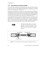
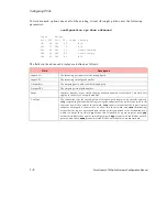
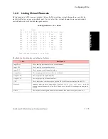
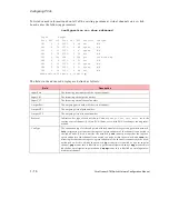
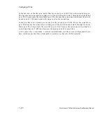
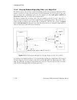
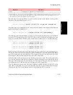
In the first line in the first pair, notice that the output port is 2E4. This is the intra-fabric port.
The 2 means the connection is coming out of the switch board in slot 2 through the intra-fabric
port. The E represents the intra-fabric port. The 4 means the connection is destined for switch
board in slot 4. 2E4 then becomes the input port in the second line.
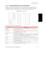
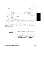
In the first line in the second pair, notice that the output port is 4E2. This is the intra-fabric
port. The 4 means the connection is coming out of the switch board in slot 4 through the intra-
fabric port. The E represents the intra-fabric port. The 2 means the connection is destined for
switch board in slot 2. 4E2 then becomes the input port in the second line.
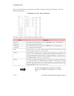
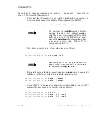
At the same time, a command is entered automatically into the current configuration data-
base, which means that this virtual path is created every time the SCP is restarted.
Summary of Contents for forerunner series
Page 6: ......
Page 16: ...TOC 10 ForeRunner ATM Switch Network Configuration Manual Table of Contents ...
Page 20: ...LOF 4 ForeRunner ATM Switch Network Configuration Manual List of Figures ...
Page 22: ...LOT 2 ForeRunner ATM Switch Network Configuration Manual List of Tables ...
Page 30: ...viii ForeRunner ATM Switch Network Configuration Manual Preface ...
Page 144: ...3 58 ForeRunner ATM Switch Network Configuration Manual Configuring an Emulated LAN ...
Page 180: ...6 12 ForeRunner ATM Switch Network Configuration Manual ATM Forum PNNI ...
Page 220: ...9 6 ForeRunner ATM Switch Network Configuration Manual Configuring Timing ...
Page 300: ...D 24 ForeRunner ATM Switch Network Configuration Manual Configuring FramePlus Modules ...
Page 308: ...Acronyms 8 ForeRunner ATM Switch Network Configuration Manual Acronyms ...
Page 346: ...Glossary 38 ForeRunner ATM Switch Network Configuration Manual Glossary ...
Page 352: ...Index 6 ForeRunner ATM Switch Network Configuration Manual Index ...

