6 - 6
ForeRunner ATM Switch Network Configuration Manual
ATM Forum PNNI
6.3.2 Dynamic Leaking of Reachability Information
This feature allows dynamic leaking of reachability information between the single FT-PNNI
node and the single PNNI node within a gateway switch. It may also be used to control the
leaking of reachability information between two PNNI peer groups. Using split switches, it
possible to connect and exchange reachability information between any number of PNNI peer
groups. This dynamic leaking is controlled using the following user-configurable settings:
grouping of nodes within a switch into areas and domains, and configuring policies that allow
you to summarize, suppress, or advertise reachability addresses between peer groups. See
Section 6.3.2.3.1 for more information about policies.
6.3.2.1 Areas
An area is a subset of nodes within a domain that are contiguous and that together execute a
link state routing protocol to exchange reachability information dynamically among them-
selves. Because of the database exchange protocol, two nodes that belong to an area will have
identical copies of the link-state topology database. Using ForeThought 5.2.x, an area can be
one of the following:
•
a non-hierarchical PNNI network (i.e., a single PNNI peer group because only the
lowest-level peer group is implemented)
•
a hierarchical FT-PNNI network (i.e., a multiple FT-PNNI peer group system
using hierarchy)
•
a non-hierarchical FT-PNNI network (i.e., a single FT-PNNI peer group)
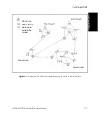
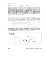
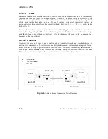
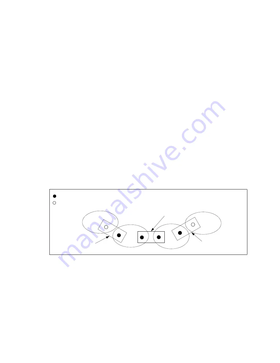
Split switches can be used to connect two PNNI areas and gateway switches can be used to
connect an FT-PNNI area and a PNNI area, as shown in Figure 6.2. The only restriction in con-
figuring areas is that a FT-PNNI area cannot adjoin another FT-PNNI area.
Figure 6.2 -
Split Switches and Gateway Switches Connecting Areas
FT-PNNI node
PNNI node
Area A
Area B
Area C
Area D
Switch S1
Switch S2
Switch S3
Summary of Contents for forerunner series
Page 6: ......
Page 16: ...TOC 10 ForeRunner ATM Switch Network Configuration Manual Table of Contents ...
Page 20: ...LOF 4 ForeRunner ATM Switch Network Configuration Manual List of Figures ...
Page 22: ...LOT 2 ForeRunner ATM Switch Network Configuration Manual List of Tables ...
Page 30: ...viii ForeRunner ATM Switch Network Configuration Manual Preface ...
Page 144: ...3 58 ForeRunner ATM Switch Network Configuration Manual Configuring an Emulated LAN ...
Page 180: ...6 12 ForeRunner ATM Switch Network Configuration Manual ATM Forum PNNI ...
Page 220: ...9 6 ForeRunner ATM Switch Network Configuration Manual Configuring Timing ...
Page 300: ...D 24 ForeRunner ATM Switch Network Configuration Manual Configuring FramePlus Modules ...
Page 308: ...Acronyms 8 ForeRunner ATM Switch Network Configuration Manual Acronyms ...
Page 346: ...Glossary 38 ForeRunner ATM Switch Network Configuration Manual Glossary ...
Page 352: ...Index 6 ForeRunner ATM Switch Network Configuration Manual Index ...

