background image

A - 18

ForeRunner

 ATM Switch Network Configuration Manual

Configuring SNMP

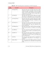
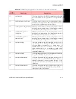
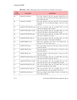
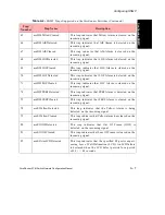
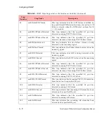
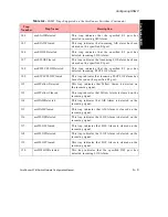
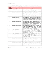
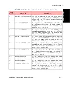
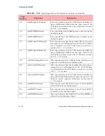
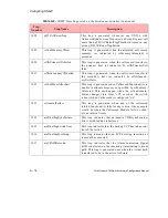
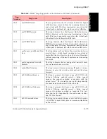
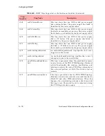
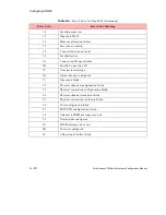
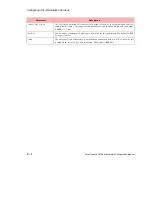
Table A.3 defines the message types and the message requests for Trap 2003.

Table A.3 - 

Message Type Encodings for Trap 2003

MessageType

Message Request

0

Configure network module

1

Configure port

2

Send egress Fdl

4

Network module reset

5

Port  reset

6

Configure a channel/service

7

Request channel/service configuration

8

Request port configuration

9

Request connection configuration

10

Channel/service reset

17

Configure LEDs

28

Request application revision

29

Create a FUNI service

30

Create a Frame Relay service

31

Request to change service admin status

32

Request to enable/disable service statistics

33

Request to enable/disable network module statistics

34

Request to enable/disable network module admin status

35

Request to enable/disable port admin status

36

Delete a service

37

Create a Frame Relay connection

38

Create a FUNI connection

40

Request to enable/disable connection admin status

41

Request to enable/disable service egress rate enforcement

Summary of Contents for forerunner series

Page 1: ...tware Version 5 2 x FORE Systems Inc 1000 FORE Drive Warrendale PA 15086 7502 Phone 724 742 4444 FAX 724 742 7742 http www fore com ForeRunner ATM Switch MANU0148 04 Rev A 5 14 98 Network Configuration Manual ...

Page 2: ...ulting from the furnishing performance or use of this publication Information published here is current or planned as of the date of publication of this document Because we are improving and adding features to our products continuously the information in this document is subject to change without notice RESTRICTED RIGHTS LEGEND Use duplication or disclosure by the government is subject to restrict...

Page 3: ...t you must inform the telephone company of the following information 3 If the unit appears to be malfunctioning it should be disconnected from the telephone lines until you learn if your equipment or the telephone line is the source of the trouble If your equipment needs repair it should not be reconnected until it is repaired 4 If the telephone company finds that this equipment is exceeding toler...

Page 4: ...the power utility telephone lines and internal metallic water pipe system if present are connected together This precaution may be particularly important in rural areas Caution Users should not attempt to make such connections themselves but should contact the appropriate electric inspection authority or electrician as appropriate E1 AND E3 NOTICE The E1 NM 6 E1C NM 2 E1C NM 8 E1D and NM 4 E1D and...

Page 5: ...y Equipment EN 50082 1 Electromagnetic compatibility Generic immunity standard Part 1 Residential commercial and light industry IEC 1000 4 2 Electromagnetic compatibility for industrial process measurement and control equipment Part 2 Electrostatic discharge requirements IEC 1000 4 3 Electromagnetic compatibility for industrial process measurement and control equipment Part 3 Radiate electromagnet...

Page 6: ......

Page 7: ...ing and Terminating Paths 1 6 1 3 Listing Virtual Paths 1 7 1 3 1 Listing Through Paths 1 7 1 3 2 Listing Originating and Terminating Paths 1 9 1 4 Virtual Channels 1 11 1 4 1 Smart Permanent Virtual Circuits 1 14 1 4 2 Listing Virtual Channels 1 15 1 5 Creating PVCs and SPVCs 1 17 1 5 1 Creating a Through Path 1 18 1 5 2 Creating an Originating or Terminating Path 1 21 1 5 2 1 Shaping Multiple Or...

Page 8: ...ARP Servers 2 6 2 3 1 Theory 2 6 2 3 2 Configuring a FORE Switch to be an ARP Server 2 7 2 3 3 Classical IP Operation 2 8 2 3 4 Operational Issues 2 9 2 4 Classical IP PVCs 2 10 2 4 1 Theory and Configuration 2 10 2 4 2 Revalidation and Removal 2 10 2 5 Configuring the Network 2 11 2 5 1 Third Party Host with No ILMI and No RFC 1577 Support 2 12 2 5 2 Third Party Switch with ILMI and No RFC 1577 S...

Page 9: ...You Begin 3 23 3 6 1 2 LECS Configuration File Syntax 3 24 3 6 1 3 Defining an ELAN 3 30 3 6 1 4 Defining a Client 3 31 3 6 1 5 LECS Control Parameters 3 32 3 6 1 6 LECS MPOA Parameters 3 33 3 6 2 Sample LECS Configuration File 3 35 3 6 3 Starting the LAN Emulation Services 3 38 3 6 3 1 Starting the LECS 3 38 3 6 3 2 Starting the DLE LES BUS Peer Servers 3 40 3 6 4 Starting the LEC s and Joining a...

Page 10: ... 4 2 2 1 The Initialization Process 4 4 4 2 2 2 The Connection Process 4 5 4 2 2 3 Multicast and Broadcast Packets 4 5 4 2 2 4 Accessing Fast Ethernet and FDDI Networks 4 5 4 2 2 5 Multiple ELANs 4 6 4 2 2 6 Distributed LAN Emulation 4 6 4 2 2 7 Automatic ELAN Selection 4 6 4 2 2 8 Intelligent BUS 4 6 4 3 An Introduction to Multi Protocol Over ATM 4 7 4 3 1 LANE Without MPOA 4 7 4 3 2 Why MPOA 4 8...

Page 11: ...Protocol 6 1 6 1 2 Database Exchange Protocol 6 2 6 1 3 Flooding Protocol 6 2 6 1 4 Path Computation 6 2 6 1 5 Hierarchical Routing 6 3 6 2 PNNI Signalling Protocol 6 4 6 2 1 Source Routing 6 4 6 2 2 Crankback 6 4 6 3 Internetworking between PNNI and FT PNNI 6 5 6 3 1 Gateway Switches and Split Switches 6 5 6 3 2 Dynamic Leaking of Reachability Information 6 6 6 3 2 1 Areas 6 6 6 3 2 1 1 Peer Grou...

Page 12: ...xamples of Invalid Configurations 7 16 7 4 Allowable Combination of Traffic Parameters 7 18 7 4 1 PNNI 1 0 UNI 4 0 7 18 7 4 1 1 Service Categories 7 18 7 4 1 2 Allowable Combination of Traffic Parameters 7 18 7 4 2 UNI 3 X 7 19 CHAPTER 8 Security 8 1 Configuring Userids 8 1 8 1 1 Login Authentication Method 8 3 8 1 1 1 Local Authentication 8 3 8 1 1 2 SecurID Authentication 8 3 8 1 1 2 1 SecurID P...

Page 13: ... Statistics 8 12 8 3 NSAP Filtering 8 13 8 3 1 Filters and Templates 8 13 8 3 2 NSAP Filtering Lookup 8 14 8 3 3 NSAP Filtering Statistics 8 14 CHAPTER 9 Configuring Timing 9 1 Overview 9 1 9 2 Timing Modes 9 1 9 3 Switchclock 9 2 9 3 1 Failover of the Switchclock 9 2 9 4 Port Level Timing 9 3 9 5 Timing Configuration Examples 9 4 9 5 1 Configuring Timing on an ASX 200BX or ASX 200WG 9 4 9 5 2 Con...

Page 14: ...ne C 10 C 3 1 1 Migration Starting with the Backbone C 10 C 3 1 1 1 Migration Overview C 11 C 3 1 1 1 1 Upgrade the Switches C 11 C 3 1 1 1 2 Convert the Backbone C 11 C 3 1 1 1 3 Convert the Individual Peer Groups C 14 C 3 1 2 Migration Starting with the Peer Groups C 19 C 3 1 2 1 Overview of the Migration C 19 C 3 1 2 1 1 Upgrade the Switches C 19 C 3 1 2 1 2 Convert Peer Group C C 19 C 3 1 2 1 ...

Page 15: ...Frame Relay Profiles D 12 D 5 2 Creating the Services for Frame Relay D 13 D 5 3 Creating Frame Relay PVCs D 14 D 5 4 Configuring Frame Relay SPVCs D 15 D 5 4 1 Creating a Frame Relay SPANS SPVC D 15 D 5 4 2 Creating a Frame Relay PNNI SPVC D 16 D 6 Configuring FUNI D 17 D 6 1 Changing the Application Key D 17 D 6 2 Creating the Profiles for FUNI D 18 D 6 3 Creating FUNI Services D 19 D 6 4 Creati...

Page 16: ...TOC 10 ForeRunner ATM Switch Network Configuration Manual Table of Contents ...

Page 17: ... 3 1 13 Figure 1 12 Virtual Channels Created on Originating Path C2 2 1 13 Figure 1 13 The Path of a Cell Via SPVCs 1 14 Figure 1 14 PVPs Looped through Port 1A2 and Output on Port 1A1 to WAN 1 24 Figure 1 15 PVPs Coming in Port 1A1 from WAN and Looped through Port 1A2 1 25 CHAPTER 2 Configuring Classical IP Figure 2 1 Configuring a Third Party Host with No ILMI and No RFC 1577 Support 2 12 Figure...

Page 18: ... Multiple Servers in Operation 3 19 Figure 3 17 Failure of One ELAN Server and the Recovery Process 3 19 Figure 3 18 ELAN Re established Using the Second Server 3 20 Figure 3 19 Sample LECS Configuration File Part One of Two 3 36 Figure 3 20 Sample LECS Configuration File Part Two of Two 3 37 CHAPTER 4 MPOA Figure 4 1 An Example of an ELAN 4 4 Figure 4 2 LANE without MPOA 4 7 Figure 4 3 LANE with ...

Page 19: ...ous Backbone C 10 Figure C 10 C 1 and A 1 as Gateway Switches C 12 Figure C 11 Peer Group Severed from the Rest of the FT PNNI Area C 13 Figure C 12 Peer Group C before the Conversion to PNNI C 14 Figure C 13 C 1 and C 2 Not Part of Peer Group C C 16 Figure C 14 A Completely Converted PNNI Network C 18 Figure C 15 C 6 as a Gateway C 20 Figure C 16 Peer Group C Fully Migrated to PNNI C 22 Figure C ...

Page 20: ...LOF 4 ForeRunner ATM Switch Network Configuration Manual List of Figures ...

Page 21: ... and Version Combinations 7 12 Table 7 4 Invalid Type and Version Combinations 7 14 Table 7 5 Valid Scope and Mode Combinations 7 15 Table 7 6 Invalid Scope and Mode Combinations 7 16 Table 7 7 UNI 3 1 Allowable Combination of Traffic Parameters in ForeThought 5 2 x 7 20 CHAPTER 8 Security Table 8 1 Possible Login Scenarios 8 2 APPENDIX A Configuring SNMP Table A 1 ASX 200WG ASX 200BX Port Numberi...

Page 22: ...LOT 2 ForeRunner ATM Switch Network Configuration Manual List of Tables ...

Page 23: ...erview of LAN Emulation LANE and Multi Protocol Over ATM MPOA Chapter 5 ForeThought PNNI Provides an overview of ForeThought PNNI and shows how this scalable routing and signalling protocol can be used to simplify large network topologies Chapter 6 ATM Forum PNNI Provides an overview of ATM Forum PNNI and shows how this scalable routing and signalling protocol can be used to simplify large network...

Page 24: ...com 3 Telephone questions to support at 800 671 FORE 3673 or 724 742 6999 4 FAX questions to support at 724 742 7900 Technical support for customers outside the United States should be handled through the local distributor or via telephone at the following number 1 724 742 6999 No matter which method is used to reach FORE Support customers should be ready to pro vide the following A support contra...

Page 25: ...names that appear within the text of this manual are represented in the following style using the flush cache command clears the bridge cache Subsystem names that appear within the text of this manual are represented in the following style to access the bridge subsystem Parameter names that appear within the text of this manual are represented in the following style using seg list allows you to sp...

Page 26: ...uct the system or currently loaded software and is indicated as follows WARNING Hazardous voltages are present To reduce the risk of electrical shock and danger to personal health follow the instructions carefully CAUTION statements contain information that is important for proper installation opera tion Compliance with CAUTION statements can prevent possible equipment damage and or loss of data a...

Page 27: ... for applicable wavelengths and durations These lasers are safe under reasonably foreseeable conditions of operation Do not view beam with optical instruments Single mode fiber optic network modules contain Class 1 lasers NOTE This Laser Notice section only applies to products or components containing Class 1 lasers Class 1 Laser Product This product conforms to applicable requirements of 21 CFR 1...

Page 28: ... the equipment Dangerous voltages may be present Conductive foreign objects could produce a short circuit that could cause fire electric shock or damage to your equipment Modifications to Equipment Do not make mechanical or electrical modifications to the equipment FORE Systems Inc is not responsible for regulatory compliance of a modified FORE product Placement of a FORE Systems Product CAUTION T...

Page 29: ...or To reduce the risk of electrical shock do not plug FORE Systems products into any other type of power system Contact your facilities manager or a qualified electrician if you are not sure what type of power is supplied to your building WARNING Your FORE Systems product is shipped with a grounding type 3 wire power cord To reduce the risk of electric shock always plug the cord into a grounded po...

Page 30: ...viii ForeRunner ATM Switch Network Configuration Manual Preface ...

Page 31: ...rmine the correct output port VPI and VCI for the cell For example an ATM switch fabric can be con figured such that any cell received on port A1 with VPI VCI 0 32 is switched to port B2 with VPI VCI 0 35 The translation from input port VPI and VCI to output port VPI and VCI is achieved via a mapping table in the switch fabric s memory The VCI value of cells does not change as the cell is switched...

Page 32: ... following sections is to explain how to create the necessary mappings to establish these virtual paths and virtual channels in a net work of ForeRunner ATM switches ForeRunner ATM ForeRunner ATM VPI 1 VCI 37 cell ForeRunner ATM ForeRunner ATM cell VPI 1 VCI 35 cell VPI 2 VCI 33 port A4 port B4 port D1 port B1 port A1 port B3 port C1 Workstation Q Workstation P Switch A Switch B Switch C Switch D ...

Page 33: ...own as virtual path terminators VPTs VPCs allow virtual paths to be cross connected at a switch node while VPTs allow virtual channels VCCs to be cross connected or switched at a switch node Figure 1 2 Virtual Channels in a Virtual Path A single virtual path can be used to route many virtual channels through the ATM network Because a virtual path simply routes virtual channels through the network ...

Page 34: ...ough an ATM switch fabric When a cell is received by a switch fabric on a through path the VPI is examined to determine the output port and VPI The VCI component of the ATM header remains unchanged and can have any value So all of the channels within the through path are switched correctly without altering the VCI value of cells on these channels Four parameters are needed to define a through path...

Page 35: ...th the through path B1 20 C1 20 If a cell is received on port C1 with VPI 20 it is not transmitted on port B1 with a new VPI 20 In order for this to happen the through path C1 20 B1 20 must exist as well Since through paths are unidirectional two through paths are necessary for bidirectional communication Figure 1 6 Through Paths are Unidirectional switch fabric cell cell VPI 20 VPI 10 B4 A4 VCI X...

Page 36: ...mation Originating and terminating paths are the endpoints of virtual paths and are used primarily for bandwidth allocation The bandwidth allocated to originating and terminating paths is used to control the amount of virtual channel VCC bandwidth entering or leaving a virtual path The total guaranteed bandwidth used by virtual channels on an originating path or a terminating path cannot exceed th...

Page 37: ...Output Port VPI Port VPI UPC Prot Name 3B1 40 3B4 40 0 pvc customer_a 3B1 75 3B5 75 0 pvc customer_b 3B2 95 3B3 95 0 pvc customer_e 3B6 62 3B2 62 0 pvc customer_c 3B6 68 3B3 68 0 pvc customer_d The fields in this display are defined as follows Field Description Input Port The incoming port number of the through path Input VPI The incoming virtual path number Output Port The outgoing port number of...

Page 38: ...ber Shape Indicates whether or not traffic shaping has been enabled for this path This field only applies to the Series C network modules ConType The connection type for the endpoints of this path with respect to a particular network Orig originating means that the ingress egress endpoint of the path is connected to the source node which is outside the network tran transit means that the ingress e...

Page 39: ...ginate 1CTL 0 N A 7 6K 1 1023 30 pvc The fields in this display are defined as follows Field Description Input Port The incoming port number of the vpt Shows originate if it is an originating path Input VPI The incoming virtual path number Output Port The outgoing port number of the vpt Shows the number of the output port of the vpt Shows terminate if it is a terminating path Output VPI The outgoi...

Page 40: ...l path number Output Port The outgoing port number of the vpt Shows terminate if it is a terminating path Output VPI The outgoing virtual path number Shape Indicates whether or not traffic shaping has been enabled for this originating vpt This field only applies to the Series C network modules VBROB The bandwidth overbooking level assigned to this vpt specified as a percentage The default is 100 w...

Page 41: ...connection between two endpoints Figure 1 8 An Example of a Virtual Channel Six parameters are needed to define a virtual channel input port input VPI input VCI out put port output VPI and output VCI Virtual channels are represented by the following nota tion iport ivpi ivci oport ovpi ovci Virtual channels switch cells using both the VPI and VCI values Both the VPI and VCI values may change when ...

Page 42: ...l is received on port D1 with VPI 8 and VCI 2 it is not transmitted out port C3 with VPI 7 and VCI 12 An addi tional channel namely D1 8 2 C3 7 12 would have to exist Figure 1 10 Virtual Channels are Unidirectional Before a virtual channel can be created the corresponding terminating and originating paths must exist For example before the channels shown on the switch fabric in Figure 1 11 can be c...

Page 43: ...se examples the terminating path C3 3 and originating path C2 2 must have enough bandwidth allocated to support the total bandwidth used by the virtual channels see Figure 1 7 C3 3 45 A3 9 100 C3 3 50 C2 3 98 C3 3 80 A1 7 88 C3 3 123 A1 3 123 Orig Term Switch or Host A Switch or Host B Switch or Host C Switch or Host D Switch or Host E ForeRunner ATM Switch A2 7 120 C2 2 120 C2 3 67 C2 2 37 C3 11 ...

Page 44: ...nsfer SPVCs are more robust than PVCs If a link carrying a PVC goes down then the PVC goes down If a link carrying a SPVC goes down and there is an alternate route then the end switch fabrics of the SPVC automatically reroute the SPVC around the failed link As shown in Figure 1 13 interswitch links exist between the ForeRunner switches The end points exist at switch A and switch E If a link goes d...

Page 45: ... 14 3CTL 0 52 0 spans N A 3B2 0 15 3CTL 0 51 spans N A Press return for more q to quit q The fields in this display are defined as follows Field Description Input Port The incoming port number of the virtual channel Input VPI The incoming virtual path number Input VCI The incoming virtual channel number Output Port The outgoing port number of the virtual channel Output VPI The outgoing virtual pat...

Page 46: ...ng port number of the virtual channel Output VPI The outgoing virtual path number Output VCI The outgoing virtual channel number Protocol Indicates what type of channel this is Can be spans pvc uni spvc or rcc rcc is the routing control channel 0 18 on PNNI links over which PNNI exchanges routing infor mation ConType The connection type for the endpoints of this channel with respect to a particula...

Page 47: ...rtual path terminator originating or terminating path a permanent virtual channel through the network a smart permanent virtual channel through the network This section assumes that the physical port parameters of the switches have already been con figured and that the ATM network module traffic models have been set appropriately For more information about these configurations see the ATM Manageme...

Page 48: ...hich paths are being used by which cus tomers Can be up to 32 ASCII characters long inctype orig tran term The path connection type for the incoming path For billing purposes it denotes on which switch this path is arriving Orig originating means that the ingress endpoint of the path is connected to the source node which is outside the network tran transit means that the ingress endpoint of the pa...

Page 49: ...ration vpc new 2a1 1 2e4 1 myswitch configuration vpc new 2e4 1 2a1 1 myswitch configuration vpc new 4b1 1 4e2 1 myswitch configuration vpc new 4e2 1 4b1 1 shapeivpi vpi 2 The incoming VPI for this through path When the traffic shaping port is not the port con nected to the WAN a through path must be created from the WAN port to the traffic shap ing port Cells arrive from the network at the traffi...

Page 50: ... 2E4 then becomes the input port in the second line In the first line in the second pair notice that the output port is 4E2 This is the intra fabric port The 4 means the connection is coming out of the switch board in slot 4 through the intra fabric port The E represents the intra fabric port The 2 means the connection is destined for switch board in slot 2 4E2 then becomes the input port in the s...

Page 51: ...dex rtvbr none default qosindex nrtvbr none default qosindex ubr none default qosindex abr none default qosindex NOTE The qosindex must exist conf qosext new before it can be applied to the originating terminating path These parameters are defined as follows Parameter Description port The port number for this vpt vpi The path number for this vpt term Specifies that the vpt to be created is a termi...

Page 52: ...ugh path that goes from the looping port to the WAN port This option is also used when creating the through path that connects from the WAN port to the looping port The through path loopvpi should be the same vpi as the terminating path on the looping port See Section 1 5 2 1 for more information vbrob The bandwidth overbooking level for this vpt specified as a percentage Valid values are integers...

Page 53: ... create the terminating side also y y The following is an example of how to delete a terminating path myswitch configuration vpt del 3b4 88 term Would you like to delete the originating side also y y The following is an example of how to delete an originating path myswitch configuration vpt del 3b3 99 orig Would you like to delete the terminating side also y y If you do not specify term or orig th...

Page 54: ...th s This port is put in either physical or diagnostic loopback and is configured with the new option loopvpi under conf vpt new The other port provides the actual output on a shaped through path so this port must be on a Series D network module Figure 1 14 PVPs Looped through Port 1A2 and Output on Port 1A1 to WAN As shown in the example in Figure 1 14 the traffic that is going out originating pa...

Page 55: ...termi nating path 1 on port 1A2 In your own network you will repeat this process on these same two ports for as many paths as you want to shape NOTE Before you configure the paths you should configure the network module that will contain the looping port to maximize the number of multicast connections On a Series C network module use model number 5 under conf module traffic c setmodel On a Series ...

Page 56: ... group is created when a PVC or PVP is configured with this UPC 2 Next delete any existing path s on the looping port as follows myswitch configuration upc conf vpt myswitch configuration vpt conf vpt del 1a2 0 NOTE By default path 0 is the only path that exists If path 1 already exists you must delete it using the command conf vpt del 1a2 1 3 Recreate the paths on the looping port using the loopv...

Page 57: ... at this point 7 Additional shaped originating paths can be added later on these same two ports as needed by repeating the steps in this section 1 5 2 2 Terminating a PVC at a Switch Sometimes it is necessary to create a PVC between a host and a switch fabric that is at a remote location In this case the PVC should be created from the host to the control port CTL of the switch and vice versa Some ...

Page 58: ...figuration atmarp newclassicalip host vpi vci interface These parameters are defined as follows Once the parameters are entered the Classical IP PVC ARP entry is created instantly by the SCP At the same time a command is entered automatically into the current CDB which cre ates this ATM ARP entry each time that the SCP is restarted Parameter Description host The IP address of the remote host vpi T...

Page 59: ...00 0000 f21b 0137 002048100be6 00 198 29 17 15 qaa0 0x47 0005 80 ffe100 0000 f21b 0137 00204810048d 00 198 29 17 52 qaa0 0x47 0005 80 ffe100 0000 f21b 0138 0020481b0138 00 The fields in this display are defined as follows Field Description IPaddress The IP address for this connection If The name of the IP interface for this connection VPI The virtual path number VCI The virtual channel number AAL ...

Page 60: ...ng purposes so you can identify which channels are being used by which customers Can be up to 32 ASCII characters long inctype The channel connection type for the incoming channel For billing purposes it denotes on which switch this channel is arriving Orig originating means that the ingress endpoint of the channel is connected to the source node which is outside the network tran tran sit means th...

Page 61: ...tra fabric port The 2 means the connection is coming out of the switch board in slot 2 through the intra fabric port The E represents the intra fabric port The 4 means the connection is destined for switch board in slot 4 2E4 then becomes the input port in the second line In the first line in the second pair notice that the output port is 4E2 This is the intra fabric port The 4 means the connectio...

Page 62: ...ter Description port The port number on the local switch fabric vpi The virtual path number on the local switch fabric vci The virtual channel number on the local switch fabric dest session The IP address of the remote switch dest port The port number on the remote switch fabric dest vpi The virtual path number on the remote switch fabric dest vci The virtual channel number on the remote switch fa...

Page 63: ...fishtank localhost myswitch configuration spvc spans new usage new port vpi vci dest session dest port dest vpi dest vci peak Kb sec source destination bidirectional myswitch configuration spvc spans new 1c1 0 49 198 29 22 46 1b1 0 50 1 5 5 Displaying SPANS SPVC Information This command allows you to display all of the SPANS SPVCs on an individual switch fabric Enter the following parameters myswi...

Page 64: ...k bandwidth allocated for this SPANS SPVC specified in Kbps Remote ID The unique number that the remote switch fabric s SCP assigned to this SPANS SPVC when it was created Remote Port The port number on the remote switch fabric Remote VPI The virtual path number on the remote switch fabric Remote VCI The virtual channel number on the remote switch fabric Switch The IP address or name of the remote...

Page 65: ...of bandwidth for the duration of the connection At connection set up time traffic that uses a VBR parameter such as a video and data makes a request for a dedicated PCR Sustainable Cell Rate SCR and Max imum Burst Size MBS Once these cell rates are defined the ATM network must be able to guarantee these rates for the duration of the connection At connection set up time ABR traffic makes a request ...

Page 66: ...le 1 1 These parameters are informally defined as follows Peak Cell Rate PCR the maximum number of cells per second Cell Delay Variation Tolerance CDVT the tolerance for variation in the inter arrival time of these cells or the amount of jitter that can be accepted by the net work Sustainable Cell Rate SCR the average rate of cell transmission for this connec tion taking bursting into account Burs...

Page 67: ... defined different types of traffic contracts to be used in conjunction with these leaky buckets The parameters that make up these types of contracts are defined as follows pcr0 PCR for cells with CLP 0 pcr01 PCR for the aggregate of the CLP 0 cells and the CLP 1 cells all cells scr0 SCR for cells with CLP 0 scr01 SCR for the aggregate of the CLP 0 cells and the CLP 1 cells all cells mbs0 MBS for ...

Page 68: ...act is for VBR traffic The first leaky bucket assesses the conformance to PCR of the aggregate of CLP 0 cells and the CLP 1 cells and the second leaky bucket assesses the conformance to SCR and BT of this same combination Cells which fail the PCR test are dropped Cells which pass the PCR test but which fail SCR and BT test are dropped The vbr0 pcr01 scr0 mbs0 tag contract is for VBR traffic It use...

Page 69: ...one of the following combinations of traffic parameters cbr pcr01 cbr0 pcr0 pcr01 tag vbr pcr01 scr01 mbs01 vbr0 pcr01 scr0 mbs0 tag These parameters are defined as follows Parameter Description index The integer index that refers to this specific traffic contract Valid index numbers are from 0 to 32 767 UPC One of the types of traffic contracts shown above The parameters in these contracts are de...

Page 70: ...epending on what is configured connections using this con tract By default noGCRA is not entered GCRA policing is enabled You must use the noGCRA option when applying a UPC contract to the outbound signalling channel using the outsigupc upc index variable under conf signalling new to prevent the outbound signalling channel from being policed aal5 The connection is using the AAL5 Adaptation Layer n...

Page 71: ...efined name associated with this UPC traffic contract This helps you remember for what traffic type this specific contract is used If you do not specify a name a default name that relates to this type of traffic contract is assigned automatically bc bits The committed burst size of a connection in bits Can only be used on a Frame Relay con nection be bits The excess burst size of a connection in b...

Page 72: ...0 of 200 cells sec or kbps an mbs0 of 250 cells or kilobits a CDVT of 1 000 microseconds and partial packet policing enabled NOTE For more information regarding traffic contracts please refer to Table 5 7 in the ATM Forum UNI 3 0 Specification NOTE PVCs that use UPC contracts containing any of the noGCRA aal5 noPktDisc PPPol and ubrTagging options are valid only when the conf port gcrapolicing con...

Page 73: ...e use of Permanent Virtual Circuits PVCs and or Switched Virtual Circuits SVCs SVC management is performed via the ATM Forum UNI 3 0 Specifica tion which specifies Q 2931 Q 2931 is a broadband signalling protocol designed to establish connections dynamically at the User Network Interface UNI Q 2931 uses Service Specific Connection Oriented Protocol SSCOP as a reliable transport protocol and all si...

Page 74: ... support routing between multiple LISs the switch software allows a switch to be configured as a member of and a router between up to four distinct LISs The host adapter software allows a host to be configured as a member of and a router between up to 16 dis tinct LISs Each LIS membership is through a separate Classical IP network interface Existing system level IP routing configuration tools are ...

Page 75: ...c sent out a SPANS interface uses FORE IP while all traffic sent out a Classical IP interface uses Classical IP The Classical IP interfaces are qaaX where X is 0 3 in switch software and are ci in host adapter software Each of the SPANS interfaces should be assigned an IP address on a subnet different than the subnets of any of the Classical IP interfaces It is permissible to place multiple SPANS ...

Page 76: ...4 FORE implements the ICD ATM format Per the UNI 3 0 specification all private networks should accept initial call set up messages containing ATM addresses with any of the approved formats and forward the calls as necessary An NSAP address consists of the following a 13 byte network side prefix The prefix is the NSAP prefix of the switch to which the host is attached a seven byte user side part Th...

Page 77: ...work address prefix is registered The host can then begin to establish new connections 2 2 3 Operating without ILMI Support If ILMI is not supported on a particular switch or host in a given network then the ATM addresses must be manually configured If another vendor s switch does not support ILMI it can not supply an ATM prefix to the hosts Therefore the user must assign a unique valid pre fix to...

Page 78: ... be obtained by using the AMI command conf atmarp arpserver show On a host the ATM address of the ARP server can be obtained by using clipconfig show remember to use the interface associated with the given LIS On a switch the ATM address of the ARP server can be configured by using the instructions found in Section 2 3 2 of this manual On a host the ARP server address is configured into the host a...

Page 79: ... SCP for the relevant inter face qaa0 qaa3 using the following AMI command configuration atmarp getnsap interface For example configuration atmarp getnsap qaa0 qaa0 NSAP address 47000580ffe1000000f12400de0020481900de00 2 Set the NSAP address of the ARP server to be the ATM address of the interface that you displayed in step 1 using the following AMI command conf atmarp arpserver set NSAPaddress in...

Page 80: ... no mechanism for ARP servers to exchange mapping information with each other it is imperative that each LIS be configured with only one ARP server When a host wants to communicate with another host in its LIS it first sends an ARP request to the ARP server containing the IP address to be resolved When an ARP reply is received from the ARP server the host creates an entry in its ARP cache for the ...

Page 81: ...Classical IP wants to initiate connections the IP to ATM address mappings of the destination hosts should be put in its ARP cache again as static entries By using static ARP entries in the above fashion the ability for all hosts to communicate is maintained There are some restrictions on the number of hosts that can be maintained dynamically They are as follows In the default configuration a host ...

Page 82: ...the PVC as well as receive on the PVC The IP datagrams are sent over the PVC using AAL5 with LLC SNAP encapsulation 2 4 2 Revalidation and Removal Normally the device driver periodically checks that its PVCs are still established and func tioning A host revalidates a PVC by sending InARP requests over the PVC if the user speci fies that revalidation should occur by using the reval option to clipar...

Page 83: ...e ideal scenario is for all hosts and switches in the net work to have support for both ILMI and for RFC 1577 Classical IP over ATM However when using other vendors equipment this may not be the case This section describes how to configure a network with the following scenarios Configuring a third party host that has no ILMI and no RFC 1577 support Configuring a third party switch that has ILMI su...

Page 84: ... Before beginning this process be sure that ForeThought software is installed and running on the FORE equipment 2 Using the configuration software of the third party host assign that host an NSAP address that has the same prefix as the switch fabric to which it is connected 3 Configure the switch that is the ARP server so that it has a static route to the third party host using the following AMI c...

Page 85: ...MI was set in the process ILMI dynamically performs address registration for all of the hosts 2 Configure a static ATM route to the third party switch on FORE switch B that is physically connected to the third party switch using the following AMI command conf atmr ftpnni staticroute new NSAP mask port port vpi vpi Be sure to use a network mask value of 104 3 Configure two static NSAP routes on the...

Page 86: ...2 Statically configure the non FORE hosts with ATM addresses edit the firmware download script using the same switch prefix for all of the hosts 3 Configure a static ATM route to the third party switch on FORE switch B that is physically connected to the third party switch using the AMI command conf atmr ftpnni staticroute new NSAP mask port port vpi vpi Be sure to use a network mask value of 104 ...

Page 87: ... ASX 200WG ASX 200BX ASX 1000 or LE 155 switch or in a UNIX workstation running Solaris 2 5 2 5 1 or 2 6 The LES BUS pair may reside either in a PowerHub 7000 an ASX 200WG ASX 200BX ASX 1000 or LE 155 switch or in a UNIX workstation running Solaris 2 5 2 5 1 or 2 6 An additional software feature is Distributed LAN Emulation DLE which provides load sharing and fault tolerance to the ELAN The curren...

Page 88: ...ystem as the LES BUS or in a separate physical system For example the LECS could reside in a switch while the LES BUS reside in a work station In ForeThought 5 2 x software the LECS is supported only on ForeRunner switches and on systems running Solaris The LES BUS are supported only on ForeRunner switches on PowerHub 7000s and on systems running Solaris The functional interconnections of a simple...

Page 89: ...ough ForeThought PNNI ATM Forum PNNI or IISP will locate the closest active LES which is using the anycast address 3 2 3 LAN Emulation Server LES The LES implements the control coordination function for the ELAN The LES provides the service of registering and resolving MAC addresses to ATM addresses A LEC registers its own address with the LES A LEC also queries the LES when the client wishes to r...

Page 90: ...ion must be maintained for the duration of the LEC s partic ipation in the ELAN Control Distribute Connection a unidirectional point to multipoint VCC set up by the LES to the LEC This connection must be maintained for the duration of the LEC s participation in the ELAN Multicast Send Connection a bidirectional point to point VCC set up by the LEC to the BUS for sending multicast data to the BUS T...

Page 91: ...guration Manual 3 5 Configuring an Emulated LAN Configuring an Emulated LAN Figure 3 2 ELAN Operation CONFIGURATION DIRECT CONTROL DIRECT CONTROL DISTRIBUTE MULTICAST SEND MULTICAST FORWARD DATA DIRECT LECS LES BUS LEC1 LEC2 engineering ...

Page 92: ... an address that is locally configured on LEC1 Once it knows the location of the LECS LEC1 establishes a configuration direct connection to the LECS When connected the LECS provides LEC1 with the information necessary to con nect to the ELAN it wishes to join This information includes such parameters as the ATM address of the ELAN s LES the type of LAN being emulated the maximum packet size and th...

Page 93: ...eived from the LECS then the LES gives the LEC permission to join If verification is not received from the LECS the LES rejects the join request and the LEC is dropped The LES assigns LEC1 a unique identifier and LEC1 registers its own MAC and ATM addresses with the LES The LES maintains a table containing the MAC addresses and corre sponding ATM addresses of all members of the ELAN At this point ...

Page 94: ...he desti nation address of LEC2 This path will be used for subsequent data transfers Before LEC1 begins to use this connection it first sends a flush packet via the BUS to the destination LEC2 When LEC2 acknowledges receipt of this packet signifying that the BUS path is empty only then does LEC1 begin to use the data direct connection for data transfer This process ensures that the network protoco...

Page 95: ...e current LANE service model which uses a single LES and BUS for each ELAN This section first describes a simple example of the single server model and then gives a detailed overview of the DLE model 3 4 1 Single Server LANE Services Model Figure 3 3 shows the topology of a single server supporting an ELAN In this example the LECs are hosts that are using IP and the LES and BUS are running on the ...

Page 96: ...Cs registered in the ELAN Figure 3 4 Broadcast IP ARP Request When LEC 3 receives the IP ARP request it recognizes that it is the intended destination and therefore attempts to send an IP ARP response to LEC 1 whose MAC address was supplied in the ARP request packet As shown in Figure 3 5 the delivery of the ARP response is a three step process LEC 3 sends an LE ARP query to the LES asking for the...

Page 97: ... number of LECs in a single ELAN is limited by the number of virtual circuits that the single LES BUS can establish through their platform s ATM port This usually limits the ELAN to about 500 LECs Clusters of LECs that are geographically separated from the LES BUS may have poor throughput even when connecting to each other because address queries and broadcasts may traverse slow wide area links A ...

Page 98: ... and the other includes individual point to point connections to each peer for directed control traffic Each DLE peer server that supports the ELAN is responsible for registering and giving reports about the LECs that are attached to it directly Each DLE peer server propagates this informa tion to both its locally attached LECs and its peers NOTE Each device running a DLE peer server must use Fore...

Page 99: ...peer servers Figure 3 7 IP ARP Broadcast from LEC 1 to LEC 9 Upon receiving the broadcast from the first DLE peer server the peers re distribute the packet to their own locally attached LECs as shown in Figure 3 8 so the packet arrives its actual destination at LEC 9 Figure 3 8 Re distributing the Broadcast across DLE Peer Servers NOTE The peers do not re distribute the packet to other peers this ...

Page 100: ...e 3 10 the second DLE peer server is attached to two proxy LECs LEC 4 and LEC 5 When the DLE peer server receives the LE ARP query it cannot resolve the query so the DLE peer server re distributes the query to its proxy LECs but not to its peer servers again to avoid a loop Meanwhile the first peer server has been able to resolve the LE ARP for the address of LEC 1 and has sent an LE ARP response ...

Page 101: ...N Also more VCs are available for use by other applica tions 3 4 2 2 2 Improved Performance for Remote LECs With DLE broadcast delivery and LE ARP resolution across peer servers can take a little longer than if all LECs were connected to a single server since extra processing steps and transmissions are needed However ELANs with groups of LECs in different locations can be designed for higher perf...

Page 102: ... and opens a circuit between LEC 1 and port N 3 LEC 1 sends a message to the LECS asking for the address of the LES for LEC 1 s ELAN The LECS responds with the ATM address of the LES and LEC 1 estab lishes a circuit to the LES and then the BUS Figure 3 12 ELAN with a Single Server and Multiple Switches Connecting to Services In Figure 3 13 when LEC 7 goes through the same process it is slightly mo...

Page 103: ... Figure 3 14 ELAN with Single Server in Operation If the single server in Figure 3 14 goes down then the entire ELAN goes down At this point the administrator must intervene and reconfigure the ELAN Eng LEC 4 Eng LEC 5 Eng LEC 6 Eng LEC 7 Eng LEC 8 Eng LEC 9 Eng LEC 1 Eng LEC 2 Eng LEC 3 LES BUS 1 Switch 1 Switch 3 Switch 2 LECS ELAN Eng Eng LEC 4 Eng LEC 5 Eng LEC 6 Eng LEC 7 Eng LEC 8 Eng LEC 9 ...

Page 104: ...er of LECs affected by a server failure is reduced and a backup server is provided for affected LECs to use Figure 3 15 shows the configuration of such an ELAN as three stations register Figure 3 15 Registrations on an ELAN with Multiple Servers LECs 1 4 and 7 are directed by their switches to the LECS The result is shown in Figure 3 16 NOTE The connection between the two servers carries broadcast...

Page 105: ...rver in a particular net work a great advantage is gained through its fault tolerance if one of the servers fails as depicted in Figure 3 17 Figure 3 17 Failure of One ELAN Server and the Recovery Process Eng LEC 4 Eng LEC 5 Eng LEC 6 Eng LEC 7 Eng LEC 8 Eng LEC 9 Eng LEC 1 Eng LEC 2 Eng LEC 3 LES BUS 1 Switch 1 Switch 3 Switch 2 LECS ELAN Eng LES BUS 2 ELAN Eng Eng LEC 4 Eng LEC 5 Eng LEC 6 Eng L...

Page 106: ...AN both Eng LES 1 and Eng LES 2 in this example 5 LEC 1 sends a request to Switch 1 to establish a connection to address N1 Switch 1 no longer believes it has a direct connection to N1 and instead uses PNNI to establish a circuit through Switches 2 and 3 to Eng LES 2 6 LEC 4 sends a request to Switch 2 to establish a connection to N1 Switch 2 may have learned from Switch 1 that it no longer offers...

Page 107: ...be dropped from the ELAN NOTE ELAN access control also works with a third party LECS The LES revalidates the client every 600 seconds since the third party LECS will not contact the LES with configuration changes You can enable ELAN access control when you are creating the LES When you use the conf lane les new command specify the secure option This indicates you want to activate a secure LES BUS ...

Page 108: ...you are configuring LANE for the first time and all of your equipment is run ning ForeThought 5 2 x use the instructions that follow here in Section 3 6 To configure an ELAN on a switch you must log into AMI on a switch running ForeThought 5 2 and use the commands found under configuration lane NOTE More information about each of these commands may be found in the AMI Configuration Commands Refere...

Page 109: ...ou want to administer You must supply the following information when building or editing the LECS configuration file Provide the name of each ELAN engineering marketing etc Provide the LAN type Ethernet or Token Ring for each ELAN Provide the MTU size for each ELAN Provide the ATM address of the LES for each ELAN If you are using DLE this address must be the anycast address for the DLE peer server...

Page 110: ...case sensitive and may not exceed 32 char acters in length clients ATM or MAC addresses miscellaneous LECS control information specified by using a group name of LECS The key field is used to denote an individual parameter within a group The value field contains the value assigned to the key Omitting the group implies that the key and value apply to all groups in the configuration file Leading and...

Page 111: ... and the maximum is 10 frames per second The default is 1 frame per second Maximum_Unknown_Frame_Time 1 Limits the number of unicast frames sent to the BUS in the specified number of seconds The default is 1 second VCC_TimeOut_Period 1200 Specifies the length of time that an idle data connection remains open before being closed The default value is 1200 seconds Maximum_Retry_Count 1 Limits the num...

Page 112: ...ocols for which MPOA resolution is supported The default is Currently the only supported value is IP ShortCut_Threshold 10 1 Specifies the number of frames per second that a LANE MPOA client LEC MPC forwards to the same destina tion via the default forwarding path before which it should begin using a shortcut The minimum number of frames is 1 frame and the maximum is 65 535 frames The minimum rate...

Page 113: ...he minimum is 3 seconds The maximum is 1 000 seconds The default is 35 seconds Resolution_GiveUp_Time 40 Specifies the minimum amount of time to wait before an MPS should give up on a pending resolution request The minimum is 5 seconds The maximum is 300 sec onds The default is 40 seconds Resolution_Default_Holding_Time 1200 Specifies the default holding time for use in NHRP Reso lution Replies Th...

Page 114: ...ies a traffic threshold that must be reached before a shortcut VCC is established for a flow Also specifies a threshold below which a shortcut VCC is no longer con sidered valid is torn down and the default forwarding path is used Both thresholds are expressed in frames per second The format is threshold threshold threshold with the set up threshold first the tear down threshold second and the set...

Page 115: ...nation UBR specifies a non shared UBR connection The format is UBR rate CBR specifies a CBR connection The format is CBR rate VBR specifies a VBR connection The format is VBR rate rate burst for CLP 0 1 cells rate burst for CLP 0 cells NRT VBR specifies a non real time VBR connection The format is NRT VBR rate rate burst for CLP 0 1 cells rate burst for CLP 0 cells ABR specifies an ABR con nection...

Page 116: ... ple the engineering ELAN could override a Maximum_Frame_Size setting of 1516 thus engineering Maximum_Frame_Size 4544 If you want to control which clients may or may not join a given ELAN two additional keys Accept and Reject whose values are comma separated lists of matching elements may be used NOTE The Accept values must be supplied if you are going to enable ELAN access control These values m...

Page 117: ...ccept Reject checking proceeds in two distinct phases first for the MAC address or route descriptor if present and second for the ATM address So even though a client might be rejected by its MAC address it can be accepted by its ATM address Therefore when configur ing the Accept and Reject rules ensure that you write them either as explicit lists of only MAC addresses or route descriptors or only ...

Page 118: ...the number of seconds before an idle Configuration Direct VCC is automatically closed by the LECS enter a statement similar to the following LECS VCC_TimeOut_Period 1200 The LECS periodically checks whether its configuration file has been modified and if it has the file is reread The length of this period in seconds is given by the Reload_Period key LECS Reload_Period 600 The Permanent_Circuits ke...

Page 119: ... may not be sent until the Resolution_Hold_Down_Time has been surpassed For example the following parameters indicate that an initial MPOA Resolution Request should be retried after 5 seconds backing off to a maximum retry time of 40 seconds and then the MPOA Resolution Request process is re initialized after 160 seconds Resolution_Initial_Retry_Time 5 Resolution_Maximum_Retry_Time 40 Resolution_H...

Page 120: ...own IP_Flows 0 0 0 0 0 202 19 88 0 24 TCP 0 23 20 1 1 600 0 1 0x0 UBR 10000 The parameters in the IP flow example are defined as follows 0 0 0 0 0 The source address prefix length 202 19 88 0 24 The destination address prefix length TCP 0 23 The protocol to which this flow applies and the source and destination ports respectively 20 1 1 600 0 1 The set up threshold the tear down threshold and the ...

Page 121: ...tch The default configuration parameters are shown with their default values These values apply to all ELANs in this configuration file unless overridden for a par ticular ELAN or client ELAN default is configured to accept any client that wishes to join The ATM address of the default LES is listed in the default Address statement If DLE is being configured for ELAN default then this address must ...

Page 122: ...ime 1 Flush_TimeOut 4 Path_Switching_Delay 6 Multicast_Send_VCC_Type Best Effort Connection_Complete_Timer 4 LAN_Type Ethernet IEEE 802 3 Maximum_Frame_Size 1516 ShortCut_Protocols IP ShortCut_Threshold 10 1 Resolution_Initial_Retry_Time 5 Resolution_Maximum_Retry_Time 40 Resolution_Hold_Down_Time 160 MPOA_KeepAlive_Time 10 MPOA_KeepAlive_Lifetime 35 Resolution_GiveUp_Time 40 Resolution_Default_Ho...

Page 123: ...tion File Part Two of Two Parameters for elan engineering engineering Address 47 0005 80 ffe100 0000 f21a 01b9 0020480605b2 11 engineering Accept 002048080011 0020481020ef engineering Maximum_Frame_Size 4544 Parameters for elan marketing marketing Address 47 0005 80 ffe100 0000 f21a 01b9 0020480605b2 21 marketing Accept 002048080011 0020481020ef ...

Page 124: ...ne lecs get host remotefile localfile For example you would enter something similar to the following configuration lane lecs get 198 29 22 46 lecs cfg 2 After you have retrieved the LECS configuration database file use the following AMI command to start the LECS service on the switch conf lane lecs new LECS Selector byte HEX db LECS database file default LES atm address LECS wka none For example t...

Page 125: ... atm forum lecs cfg The OperStatus field shows up meaning that the LECS is running Now you must start the DLE peer servers as described in the next section NOTE If you used an address other than the ATM Forum s address the WKA field would show other and that address would be displayed below the entry If you disabled the well known address the WKA field would show none NOTE If you used the default ...

Page 126: ...name bus BUS Selector Byte HEX type ethernet token ring mtu 1516 1580 4544 9234 18190 secure wka LECS ATM Address registertlvs enable disable anycast LES Anycast ATM Address peers atm addr For example you would enter something similar to the following conf lane les new 90 engineering anycast c5 0005 80 ffe100 0000 f21a 3596 0020481a3596 f0 peers 47 0005 80 ffe100 0000 f21a 10bb 0020481a10bb 90 47 ...

Page 127: ...52 0020481a3552 10 PEER 0x47 0005 80 ffe100 0000 f21a 3218 0020481a3218 44 The OperStatus field shows up meaning that the LES and the BUS are running 3 You should then configure the DLE peer servers Open an AMI session on one of the other switches that will run a DLE peer server and enter something similar to the following conf lane les new 10 engineering anycast c5 0005 80 ffe100 0000 f21a 3596 0...

Page 128: ...t can only join an Ethernet ELAN 1 To start a LEC that will attempt to join the ELAN use the following AMI command on the switch that is going to be a LEC conf lane lec new LEC Selector byte HEX ELAN name ip IP Address mask IP netmask wellknown manual manual mode options lecs LECS address or les LES address NOTE The recommended and default method for starting a LEC is to use the wellknown mode mea...

Page 129: ...Mode MACaddress IfName ELAN 1 up up 0x02 wellknown 00204815096b el0 engineering LECS 0x47 0079 00 000000 0000 0000 0000 00a03e000001 00 LES c000580ffe1000000f21a35960020481a3596f0 The OperStatus field shows up meaning that the LEC has successfully joined the ELAN NOTE If the OperStatus field shows joining this means that the LEC is still registering with the ELAN Wait a few seconds and check it ag...

Page 130: ...s are involved in upgrading your ELAN to use DLE Each of these steps is described in detail in the following sections It is recommended that you read the entire section before attempting to upgrade to DLE These steps describe the commands for a switch Refer to the corresponding User s Manual for the appropriate steps for commands for hosts PowerHubs ES 3810s or the VLAN Manager 1 Edit the LECS CFG...

Page 131: ... that is currently being used by the LECS to a workstation other than the one to which you backed up the file so you can edit the file myswitch operation flash put lecs cfg 169 144 85 195 tftpboot lecs cfg Transferred 2323 bytes of fs lecs cfg The information about the LES addresses in your old LECS CFG file may look something like this before editing Match Ordering Mktg 0 Mktg 1 Mktg 0 Address 47...

Page 132: ... like this Match Ordering Mktg Mktg 0 Mktg 1 Mktg Address c5000580ffe1000000f21c126b0020481c126b66 Mktg Accept XXXXXXXXXXXXXXXXXXXXXXXXXXXXXXXXXXXXXXXX Mktg 0 Address c5000580ffe1000000f21c126b0020481c126b66 Mktg 0 Accept XXXXXXXXXXXXXXXXXXXXXXXXXXXXXXXXXXXXXXXX Mktg 1 Address 47000580ffe1000000f21a390e0020481a390e00 Mktg 1 Accept XXXXXXXXXXXXXXXXXXXXXXXXXXXXXXXXXXXXXXXX 3 7 2 Delete the LES and B...

Page 133: ... servers have been established The last LES and BUS will be changed over at the very end of the process 3 7 3 Upgrade the Switches Running Services Upgrade each of the switches that is going to be running services to ForeThought 5 2 x using the following AMI command oper upgrade remotehost full path to remotefile Do not upgrade the switch that is running the last LES and BUS in this case Mktg 1 Th...

Page 134: ... 0000 f21c 10bb 0020481c10bb 90 Create each of the other peer servers using the same anycast address and giving them the peer address es of each peer in the ELAN In this example there is only one peer myswitch configuration lane les new 0x90 Mktg anycast c5 0005 80 ffe100 0000 f21c 126b 0020481c126b 66 peers 47 0005 80 ffe100 0000 f21c 10bb 0020481c10bb 90 47 0005 80 ffe100 0000 f21a 24f9 0020481a...

Page 135: ...s field to verify that the LECS has come up again myswitch configuration lane lecs show Index AdminStatus OperStatus Selector WKA Database 1 up up 0x00 atm forum lecs cfg 3 7 7 Recreate the LECs If you are going to upgrade any or all of the clients to ForeThought 5 2 x you should do so now Use the following AMI command to upgrade any of the clients that are running on switches oper upgrade remoteh...

Page 136: ...0000f21c126b0020481c126b66 LEC ID 13057 Discovered ELAN name Mktg 0 Configure Direct VCC 0 323 Maximum Frame Size 1516 Control Direct VCC 0 667 Control Distribute VCC 0 203 Multicast Send VCC 0 674 Multicast Forward VCC 0 205 Last Error Configure that LEC down myswitch configuration ip admin el17 down Delete all instances of the LEC including anything that had been ELAN name n myswitch configurati...

Page 137: ... of the steps in this section for each LEC Refer to the corresponding User s Manual for the appropriate steps for re creating LECs that are running on hosts PowerHubs or ES 3810s At this time you may also add any new clients to the ELAN 3 7 8 Create the Last DLE Peer After all of the LECs have been changed over and any new LECs have been added go back and change the remaining failover LES to a DLE...

Page 138: ...ECS CFG file looked like this before editing Match Ordering Mktg Mktg 0 Mktg 1 Mktg Address c5000580ffe1000000f21c126b0020481c126b66 Mktg Accept XXXXXXXXXXXXXXXXXXXXXXXXXXXXXXXXXXXXXXXX Mktg 0 Address c5000580ffe1000000f21c126b0020481c126b66 Mktg 0 Accept XXXXXXXXXXXXXXXXXXXXXXXXXXXXXXXXXXXXXXXX Mktg 1 Address 47000580ffe1000000f21a390e0020481a390e00 Mktg 1 Accept XXXXXXXXXXXXXXXXXXXXXXXXXXXXXXXXX...

Page 139: ...on with the LECS and forces the LECS to read and use the new LECS CFG file myswitch configuration lane lecs admin 1 down myswitch configuration lane lecs admin 1 up Use the show command and look at the OperStatus field to verify that the LECS has come up again myswitch configuration lane lecs show Index AdminStatus OperStatus Selector WKA Database 1 up up 0x00 atm forum lecs cfg The transfer of yo...

Page 140: ...e 1 If the LES and BUS are not co located they must be deleted and re created as co located because ForeThought 5 2 x on the switch only supports co located ser vices If the LES and BUS are already co located skip to step 2 2 Upgrade the switches that are running services 3 Re create the LES and BUS if they were not co located If the LES and BUS were already co located skip to step 4 4 Administer ...

Page 141: ... and BUS Delete the LES and BUS myswitch configuration lane les delete LES index myswitch configuration lane bus delete BUS index 3 8 1 2 1 Edit the LECS CFG File NOTE Before you edit the LECS CFG file you may wish to back it up to a host using the oper flash put command If you are using TFTP as the transfer protocol this is the default the remote host to which the FLASH file will be sent must be ...

Page 142: ...he switch es running each of the services to ForeThought 5 2 x using the following AMI command oper upgrade remotehost full path to remotefile 3 8 3 Recreate the LES and BUS Together If your LES and BUS are already co located skip to step 4 If your LES and BUS were not co located re create each LES and BUS using the following single AMI command myswitch configuration lane les new LES Selector Byte...

Page 143: ...mulated LAN 3 8 4 Administer the Services Up Administer up the LES BUS pair and the LECS on the switch es running each of the services myswitch configuration lane les admin LES index up myswitch configuration lane lecs admin LECS index up The transfer of your ELAN to ForeThought 5 2 x is now complete ...

Page 144: ...3 58 ForeRunner ATM Switch Network Configuration Manual Configuring an Emulated LAN ...

Page 145: ...Ethernet or Token Ring LAN This emulated Ethernet or Token Ring LAN is called an emulated LAN ELAN The ELAN components resolve MAC addresses to ATM addresses replace the con nectionless operation of legacy LANs with point to point connections and provide broadcast and multicast services The ELAN consists of a LANE MPOA Client LEC MPC running on each host in the ELAN and the following LANE Services...

Page 146: ...tion of the LEC MPC in an MPOA aware network is to source and sink internetwork shortcuts LAN Emulation Configuration Server LECS Runs on a Solaris workstation or a FORE Systems ATM switch Maintains information about all ELANs within the administrative domain When the LEC MPC successfully communicates with the LECS the LECS provides a list of ELANs which the LEC MPC can join The LECS may be config...

Page 147: ...h or a Solaris workstation Provides services within a single ELAN allowing broadcasts multicasts and unknown unicasts The BUS is MPOA ignorant 4 2 2 An Example LANE Configuration Figure 4 1 shows an example configuration of a single ELAN in a FORE network The ELAN includes PC Workstations each running a LEC MPC Each has a ForeRunner ATM adapter the ForeRunner driver for the adapter and one or more...

Page 148: ... address registration Optionally you can manually specify the ATM address 2 The LEC MPC establishes a connection to a LECS using an address obtained via ILMI a well known address or PVC 0 17 Optionally you can manually specify the LECS address PC1 ASX 200BX Each PC runs a LEC MPC Runs a LECS LES BUS and LEC PowerHub 7000 Fast Ethernet Ethernet FDDI ATM Runs a LEC MPC ASX 200BX PC2 PC3 PC4 PC5 PC6 ...

Page 149: ...section for a description of how the LEC MPC connects to other hosts on the ELAN 4 2 2 2 The Connection Process To send packets to another host on the ELAN 1 The LEC MPC calls the LES to map the MAC destination address into an ATM address The LES maintains a mapping table of the address of all LEC MPCs on the ELAN 2 If the LES finds an entry in its table for the destination MAC address it returns ...

Page 150: ... With this arrangement should one of the peer servers fail the clients connected to the remaining server continue to maintain connectivity while the clients that were connected to the failed server automatically re establish connectivity to the ELAN within 60 seconds 4 2 2 7 Automatic ELAN Selection To simplify configuration of the ELAN a host is allowed to join an ELAN without specifying an ELAN ...

Page 151: ...n and before packet transmission in a LAN to ATM edge device as packets move through the network LANE is one example of such a protocol It resolves datalink layer addresses into ATM addresses and establishes circuits to the destination addresses Network addresses within a subnet can be learned using LANE s broadcast support However LANE relies on physical routers to deliver packets across subnets ...

Page 152: ...troduces LANE MPOA Clients LEC MPCs and MPOA Servers MPSs and defines the protocols that are required for LEC MPCs and MPSs to communicate LEC MPCs issue queries for ATM addresses and receive replies from the MPS using these protocols MPOA also maintains interoperability with the existing infrastructure of routers MPOA Serv ers reside in routers that run standard Internetwork Layer routing protoco...

Page 153: ...ForeRunner ATM Switch Network Configuration Manual 4 9 MPOA MPOA Figure 4 3 LANE with MPOA S hortcut VCC ATM Cloud Router ELAN engineering ELAN marketing ...

Page 154: ...t contains an MPS When the ingress LEC MPC recognizes a flow rate configurable that could benefit from a shortcut and thus bypass the routed path it requests a shortcut to the destination If a shortcut is available the ingress LEC MPC sets up a shortcut VCC and forwards traffic for the destination over the shortcut An egress LEC MPC receives internetwork traffic from other LEC MPCs to be forwarded...

Page 155: ...e at each end must be running an MPS A Next Hop Resolution Protocol NHRP path must exist between MPSs The following example illustrates a typical ATM network that allows MPOA shortcuts to be employed Figure 4 4 MPOA Example Network PC Each of these runs a LEC MPC Runs a LECS LES and BUS ASX 200BX PC Each of these runs a LEC MPC Runs a LECS LES and BUS ASX 200BX PC PC Powerhub 7000 Runs Powerhub 70...

Page 156: ...is attached 2 The LEC MPC connects to an LECS to which it sends its own ATM address and the name of the ELAN it wishes to join the ELAN name is an empty string unless the LEC MPC has been site configured with an ELAN name The LEC MPC also supplies a LANE 1 0 compliant parameter identifying itself as an MPOA aware client 3 Next the LEC MPC receives the following from the LECS the name of the ELAN t...

Page 157: ...rmines if the packet traffic flow exceeds the shortcut enable trigger value set by the flow descriptors for the destination IP address s flow If the flow exceeds the trigger value the LEC MPC tries to establish a shortcut circuit to the destination LEC MPC called the egress LEC MPC If the flow does not exceed the trigger value the ingress LEC MPC simply sends the packet traffic to the gate way rou...

Page 158: ... shortcut circuit If no shortcut circuit exists it opens a new shortcut circuit and begins sending packets over it to the destination 4 3 4 5 Shortcut Teardown Application programs and networking protocol stacks are MPOA ignorant and therefore do not tear down shortcut circuits when the shortcut is no longer needed Therefore the MPOA layer itself tears down seldom used shortcuts to avoid circuit e...

Page 159: ...of FORE Systems pre standard version of PNNI ForeThought PNNI FT PNNI and its use in a multiple switch network FT PNNI is a scalable routing and signalling protocol used in networks containing multiple ForeRunner switches FT PNNI simplifies large network topologies by organizing the nodes switches in that net work into smaller groups It is this reorganization of the network topology that makes FT ...

Page 160: ...inks are refreshed periodically Since loglinks discovered as a result of hello indications are unidirectional each switch stores unidirectional loglinks with its immediate neighbor as the source and itself as the destination 5 1 2 Topology Database Exchange Each switch sends to each of its neighbors a group of loglinks from its topology database at regular intervals called the NSAP map indication ...

Page 161: ...iers FT PNNI does not distinguish between node identifiers and reachability information Thus the IDs of nodes in the FT PNNI addressing map are NSAP prefixes In the default case at the lowest level peer group the switches have a 13 byte prefix as their node ID and end systems hosts have a 19 byte prefix as their node ID 5 1 4 1 1 Switch Prefix Each switch in a FT PNNI network is configured with a ...

Page 162: ... prefix that constitute the peer group ID Each peer group has a peer group ID that uniquely identifies it from every other peer group Every node switch or end system in a particular peer group shares that same unique peer group ID thereby indicating membership to that peer group A simple example of summarizing by peer group ID can be seen in Figure 5 3 where every switch and end system although no...

Page 163: ...ached This topology is stored by each switch in its local topology database In a small local area network LAN the topology is relatively simple meaning that the switches in the LAN have a relatively small topology database to maintain As the LAN grows however and more switches are added that same database can grow to be very large in a short period of time As this topology database grows the amoun...

Page 164: ...ogies by creating a two level hierarchy In this hierarchy clusters of contiguous switches are grouped together and they are collectively summarized by a single logical node Figure 5 3 shows the same network as in Figure 5 2 after being organized into peer groups now having a two level hierarchy The subsections that follow explain the organization of these peer groups how they simplify the overall ...

Page 165: ...hought PNNI Figure 5 3 Example of FT PNNI Hierarchy Showing Lowest Level Peer Groups Peer Group D Peer Group C Peer Group B Peer Group A Peer Group Border Switch Switch Node Logical Link D 4 D 3 D 2 D 1 A 1 A 3 A 2 C 6 C 1 C 2 C 3 C 4 C 5 B 1 B 8 B 3 B 2 B 4 B 6 B 5 B 7 loglink ...

Page 166: ...er group and others but they are not aware of internal topology information of other peer groups Instead the topolo gies of other peer groups are summarized as a single reachable location known as a peer group summary node PGSN 5 2 2 Peer Group Topology To maintain an accurate and updated view of its relative location and status a switch periodi cally sends a hello indication message to every othe...

Page 167: ...hes and loglinks from border switches to PGSNs are called backbone links and considered part of the backbone topology Information regarding these backbone links is propagated across peer group boundaries during database exchange and flooding 5 2 6 Single Switch Perspective The main reason for grouping switches in large networks is to simplify each individual switch s view of the topology For examp...

Page 168: ...reRunner ATM Switch Network Configuration Manual ForeThought PNNI Figure 5 4 View of the Network from Switches in Peer Group A Backbone Link D 2 A 1 A 3 A 2 C 1 C 2 B 1 B 8 Peer Group Summary Node PGSN C D B A ...

Page 169: ...itches and groups of switches Reachability information is the data that explains how to contact a single ATM address or a group of ATM addresses that are summa rized by a single prefix This information is used to compute routes across the network The key elements of the PNNI routing protocol are as follows Hello Protocol Database Exchange Protocol Flooding Protocol Path Computation Hierarchical Ro...

Page 170: ...examined Each PTSE is acknowledged by sending a PTSE acknowledgment packet containing possibly a bundle of PTSE acknowledg ments to the sending peer If the PTSE is more recent than the copy that the receiving node has in its topology database the database copy is updated and is re flooded to all neighboring peers except the one from which the PTSE was received A PTSE sent to a neighboring peer is ...

Page 171: ... A node is a logical entity that resides in a switch and performs routing operations such as discovering other nodes in the network maintaining a topology database of its peer group exchanging that database with its neighbors and computing paths from itself to other nodes in the network The interconnection of logical group nodes form a higher level topology Logical group nodes can in turn be group...

Page 172: ... or PNNI router should use when setting up an SVC Each DTL is a source route and each entry in the DTL represents a single hop in that source route Each hop is represented by a ForeThought PNNI or PNNI node and the logical output port at that node 6 2 2 Crankback During PNNI signalling a call being processed according to a DTL may encounter a blocked node or link along the designated route Crankba...

Page 173: ...y switch A gateway switch connects a PNNI network with a FT PNNI network You can also create two PNNI nodes instead on single switch This is called a split switch A split switch connects two PNNI areas The FT PNNI and PNNI nodes within a gateway switch and the two nodes within a split switch do not share topology information but they dynamically exchange reachability infor mation to facilitate con...

Page 174: ... of nodes within a domain that are contiguous and that together execute a link state routing protocol to exchange reachability information dynamically among them selves Because of the database exchange protocol two nodes that belong to an area will have identical copies of the link state topology database Using ForeThought 5 2 x an area can be one of the following a non hierarchical PNNI network i...

Page 175: ...nique only within a domain The area ID is only useful at the border of the area Since area IDs are included in some of the routing packets distributed throughout a domain all switches belonging to the same area must be configured with the same area ID It is especially important for the nodes in split switches and gateway switches to be configured with the correct area ID Peer Group D Peer Group C ...

Page 176: ...st one area at level Li 1 or higher This means that on a given switch there can never be areas config ured that belong to more than two distinct levels Furthermore there can only be one area that belongs to the higher level 6 3 2 2 Domains A domain is a group of areas that are configured to dynamically exchange reachability infor mation with one another This allows connectivity between end systems...

Page 177: ...ain can be changed Multiple domains can be configured on a switch For each domain the following parameters can be changed The domain name which is optional can be configured for easier manageability However the name of the default domain cannot be changed The domain protocol which sets the routing protocol for the switch can be set to ftpnni pnni or gateway This parameter can also be changed on th...

Page 178: ...ring since addresses matching a broad prefix can be filtered at the split switch or gateway switch through the suppress policy then a particular service device or switch can be exempted by advertising an address within the suppressed range The summary policy is best for scalability since one address prefix is shared rather than dozens or hundreds of more specific addresses For example suppose you ...

Page 179: ...the address 3 If the longest matching policy prefix is a policy suppress the leaked address is not advertised at all 4 If the longest matching policy prefix is a policy advertise or summary the policy prefix is advertised or summarized If there are multiple leaked addresses with dif ferent scopes for which the policy prefix is longest matching then the one with the widest scope is used to determin...

Page 180: ...6 12 ForeRunner ATM Switch Network Configuration Manual ATM Forum PNNI ...

Page 181: ...CI allocation range is the range of VCI values in a path within which a signalling chan nel will allocate VCs This range defaults to the VCI range of the virtual path containing the signalling channel also referred to as the containing path NOTE If the signalling channel is a link scope signalling channel then this range applies to the containing path and all other paths within which the signallin...

Page 182: ...ual range is computed as an intersection based on the range you enter 70 200 and the range available in that VP 1 511 To display what the actual VCI range is enter the following command conf signalling show atm Admin Admin Oper Oper Port VPI SigVCI ILMIVCI MinVCI MaxVCI MinVCI MaxVCI InSigUpc OutSigService 1A1 0 5 16 32 511 32 511 0 vbr 1A2 0 5 16 32 511 32 511 0 vbr 1A3 0 5 16 32 511 32 511 0 vbr...

Page 183: ... pvc originate 1A3 65 N A 0 8K 1 120 6 pvc originate 1A4 0 N A 0 8K 1 511 6 pvc Press return for more q to quit q and you enter the following conf signalling new 1A3 65 ilmi down minvci 70 maxvci 200 then the actual range is computed as an intersection based on the range you enter 70 200 and the range available in that VP 1 120 To see what the actual VCI range is enter the following command conf s...

Page 184: ... up minvci 70 maxvci 200 the actual range is computed as an intersection based on the range you enter 70 200 the range available in that VP 1 511 and the range of the peer signalling entity 32 511 To display what the actual VCI range is enter the following command conf signalling show atm Admin Admin Oper Oper Port VPI SigVCI ILMIVCI MinVCI MaxVCI MinVCI MaxVCI InSigUpc OutSigService 1A1 0 5 16 32...

Page 185: ... 1A3 65 N A 0 8K 1 120 6 pvc originate 1A4 0 N A 0 8K 1 511 6 pvc Press return for more q to quit q and you enter the following conf signalling new 1A3 65 ilmi up minvci 70 maxvci 200 then the actual range is computed as an intersection based on the range you enter 70 200 the range available in that VP 1 120 and the range supported by the peer 32 511 To see what the actual VCI range is enter the f...

Page 186: ...at VP 1 120 and the range supported by the peer 32 180 To see what the actual VCI range is enter the following command conf signalling show atm Admin Admin Oper Oper Port VPI SigVCI ILMIVCI MinVCI MaxVCI MinVCI MaxVCI InSigUpc OutSigService 1A1 0 5 16 32 511 32 511 0 vbr 1A2 0 5 16 32 511 32 511 0 vbr 1A3 0 5 16 32 511 32 511 0 vbr 1A3 65 5 16 70 200 70 120 0 vbr 1A4 0 5 16 32 511 32 511 0 vbr 1CT...

Page 187: ...e signalling channel in an ASX 1000 cannot be a link scope signalling channel 7 2 1 VC Space The VC space of a signalling channel is the VPI VCI space within which a signalling channel can allocate connections This is determined by the allocation scope of the signalling channel and the VCI allocation range see Section 7 1 for the signalling channel The VC space of a VP scope signalling channel is ...

Page 188: ...ink scope signalling channel never uses an existing provisioned terminating originating path apart from the path that contains the sig nalling channel to allocate virtual channel connections Dynamic paths inherit the characteristics of the virtual path that contains the signalling chan nel called the containing path Therefore dynamic paths have the same VCI range as the con taining path and are el...

Page 189: ...utomatically The switch also translates signalling messages between interfaces of different types When a signalling channel is created using conf signalling new version auto then the creation is delayed until a response is obtained from the peer or until the ILMI keep alive requests time out Based on the peer response the appropriate SSCOP stack is initialized If the peer does not support the atmf...

Page 190: ...ed SSCOP 31 stack initialized error message displayed on syslog SSCOP 31 stack initialized misconfiguration SSCOP 31 stack initialized peer changes version to UNI 3 1 PNNI 1 0 UNI 3 0 UNI 3 1 UNI4 0 PNNI 1 0 Auto SSCOP 31 stack initialized error message displayed on syslog SSCOP 31 stack initialized misconfiguration SSCOP 31 stack initialized misconfiguration SSCOP 31 stack initialized SSCOP 31 st...

Page 191: ...3 1 Version 3 0 Version 3 1 Version 4 0 Version 2 0 MIB variable not supported SSCOP 31 stack initialized error message displayed on syslog SSCOP 31 stack initialized SSCOP 31 stack initialized error message displayed on syslog SSCOP 30 stack initialized version 2 0 is not supported and error message displayed on syslog SSCOP 31 stack initialized error message displayed on syslog UNI 4 0 Version 3...

Page 192: ...uni31 pnni10 uni40 type auto publicUNI IISP privateNNI privateUNI The type and version either both have to be auto or both have to be given a parameter other than auto Specifying the type as auto and hard configuring the version or vice versa is not allowed If a type is not entered then the type parameter defaults to auto Similarly the ver sion parameter defaults to auto if a version is not entere...

Page 193: ...ni30 conf sig new 1a1 0 type publicUNI version uni31 conf sig new 1a1 0 type publicUNI version uni40 conf sig new 1a1 0 type IISP version uni30 conf sig new 1a1 0 type IISP version uni31 conf sig new 1a1 0 type IISP version uni40 conf sig new 1a1 0 type privateNNI version pnni10 The first example is the default that is most often used when configuring a signalling interface Using this specificatio...

Page 194: ... type is auto conf sig new 1a1 0 type privateUNI The version is not entered auto conf sig new 1a1 0 type privateUNI version auto The version is auto conf sig new 1a1 0 type privateUNI version pnni10 pnni10 is an NNI protocol conf sig new 1a1 0 type publicUNI version pnni10 pnni10 is an NNI protocol conf sig new 1a1 0 type IISP The version is not entered auto conf sig new 1a1 0 type IISP version au...

Page 195: ... have to be auto or both have to be given a parameter other than auto Specifying the scope as auto and hard configuring the mode or vice versa is not allowed If a scope is not entered then the scope parameter defaults to auto Similarly the mode parameter defaults to auto if a mode is not entered Table 7 5 shows the valid combinations Table 7 5 Valid Scope and Mode Combinations Scope Mode autoScope...

Page 196: ...ble 7 6 Invalid Scope and Mode Combinations Invalid Combination Reason conf sig new 1a1 0 sig_mode vpAssoc The scope is not entered auto conf sig new 1a1 0 sig_alloc auto sig_mode vpAssoc The scope is auto conf sig new 1a1 0 sig_mode nonAssoc The scope is not entered auto conf sig new 1a1 0 sig_alloc auto sig_mode nonAssoc The scope is auto conf sig new 1a1 0 sig_alloc vp The mode is not entered a...

Page 197: ...face either by the user explicitly specifying type privateNNI or by specifying type auto In this case if the path is an elastic path then the operating scope becomes link and the operating mode becomes nonAssoc If the path is a non elastic path then the operating scope becomes vp and the operating mode becomes vpAssoc Therefore if a signalling interface exists between two switches on VPI 0 with on...

Page 198: ... present and the absence or presence of the best effort indi cator in octet 18 of the ATM Traffic Descriptor information element Derivation of a service category from the above information is specified in Section A9 2 Determination of ATM service Category of the ATM User Network Interface UNI Signal ling Specification Version 4 0 UNI 4 0 However ForeThought 5 2 x does not support the fol lowing fr...

Page 199: ... 3 1 specification These traffic contracts are enforced on both signalled connections as well on PNNI SPVCs The following are the allowable contracts supported by FORE s switch fabrics CBR PCR 0 PCR 0 1 CBR PCR 0 1 VBR PCR 0 1 SCR MBS 0 VBR PCR 0 1 SCR MBS 0 1 UBR PCR 0 1 NOTE Traffic contracts that do not completely characterize the traffic characteristics of a given service category are incomple...

Page 200: ...ming Required is absent these 3 codings are treated as equivalent The parameter is coded to either no indication or No or for UNI 3 1 Octet 5a Traffic Type Timing Required is absent these 3 codings are treated as equivalent A blank entry indicates that the parameter is not present Table 7 7 UNI 3 1 Allowable Combination of Traffic Parameters in ForeThought 5 2 x Broadband Bearer Class A X C X C X ...

Page 201: ...sword On a new switch running ForeThought 5 0 x or greater there are two separate default userids ami and asx Both are configured with the local authentication method with admin privi leges meaning you are allowed to use all AMI commands and all access meaning you are allowed to login to the switch using all the possible methods Both userids are assigned a null password The network administrator s...

Page 202: ...r not accessible Reject Userid not listed SecurID server accessible and SecurID server rejects userid Reject Userid not listed SecurID server accessible and SecurID server accepts userid Accept Userid listed and port not OK Reject Userid listed port OK local authentication and supplied password does not match Reject Userid listed port OK local authentication and supplied password matches Accept Us...

Page 203: ...eView see the ForeView Network Management User s Manual 8 1 1 2 SecurID Authentication When a user is configured for SecurID authentication and he or she attempts to log in the user is prompted for a login ID userid and a SecurID passcode The two part passcode consists of a secret memorized personal identification number PIN and the current code generated by the user s assigned SecurID token The p...

Page 204: ...erver software has generated for that moment 8 1 1 2 3 SecurID Server The server can run on a UNIX system or on a Windows NT system Each FORE switch has a defined set of authorized users See the AMI Configuration Commands Reference Manual for more information When a user is designated as someone who has SecurID authorization that user is not permitted access to that switch until his or her identit...

Page 205: ...stalling SecurID on a Switch The following sections describe how to install SecurID on a switch 8 1 1 2 5 1 Installing the Server Software A SecurID server must be run to implement the SecurID authentication method for users of the switch Refer to the Security Dynamics ACE Server or Client user s manuals for instruc tions about installing the software on the server 8 1 1 2 5 2 Transferring the Con...

Page 206: ...n be modified on the server itself by running sdsetup again and changing the desired parameters NOTE After the changes are made on the server use the conf security login securid get AMI command to copy the updated sdconf rec file back to all of the switches that are using that file A sample of the contents of a sdconf rec file and a description of the parameters follows Server License and Configur...

Page 207: ...a client attempts to establish communications with the server before reporting an error CLIENT TIMEOUT Specifies how many seconds should elapse between attempts to establish client server communications DES ENCRYPTION Shows if DES or Security Dynamics encryption is used for client server communications DURESS MODE Allows a user to enter a special PIN to signal that he or she is being forced to log...

Page 208: ... Token ENTER If the passcode entered by the user is accepted an AMI session to the switch is started If the server denies access to the user the following message appears on the screen Login incorrect After three unsuccessful attempts the telnet connection is torn down by the switch ADDRESSES Indicates how network devices shall have the IP addresses resolved BAD PASSCODES The number of failed logi...

Page 209: ...assword to modify passwords other than your own conf security login restore conf security login show all conf security login securid commands all conf security ipaccess commands all conf security nsapfiltering commands conf snmp sets and all debug commands The default is admin 8 1 3 AMI Access Levels The network administrator can configure four different levels of AMI access for userids serial net...

Page 210: ...nge any userid password without first entering the old local password except their own The maximum size is for a password is 512 characters Any characters are allowed except the colon character 8 1 5 Privilege Level for Unlisted Users One of the login scenarios in Table 8 1 allows users who are not listed in the switch to login provided that the SecurID server is accessible and provided that the S...

Page 211: ...resses For example an IP address of 163 26 54 6 with a mask of 255 255 255 255 means only address 163 26 54 6 is accepted against that entry However an IP address of 163 26 54 6 with a mask of 255 255 0 0 means addresses 163 26 are accepted against that entry The table can contain a maximum of 32 entries The administrator can also delete entries from the table and display the contents of the table...

Page 212: ...ch an IP address in the table of authorized addresses 8 2 2 3 All Flag If the all flag is set to allow all incoming IP packets are accepted provided that they match an IP address in the table of authorized addresses Allowing all is the default setting If the all flag is set to disallow all incoming IP packets are rejected even if they match an IP address in the table of authorized addresses 8 2 3 ...

Page 213: ...bout the last call that was rejected by the filtering process 8 3 1 Filters and Templates Each filter is composed of an ordered set of templates A template consists of the following an incoming UNI port VPI a source NSAP address mask an outgoing UNI port VPI a destination NSAP Mask an action to either accept or reject the UNI or NSAP address Masks may be wildcarded using a 0 Ports VPIs and NSAP ad...

Page 214: ...ormation does not match any of the existing templates then an answer of rejected and address unknown is given When this feature is used none of the statistics are incremented and no traps are sent 8 3 3 NSAP Filtering Statistics To display statistics for NSAP filtering use the stat nsapfilter command See the AMI Configuration Commands Reference Manual for more information about this command NSAP f...

Page 215: ...me reference signal must be distributed to every element in the network to establish one cohesive entity This time reference on ForeRunner ATM Switches is called a switchclock 9 2 Timing Modes There are two timing modes available on ForeRunner ATM Switches TCM and switch TCM mode means that all network modules that support distributed timing import their clock source from the Timing Control Module...

Page 216: ...f the net work modules in all of the fabrics will use the same timing source 9 3 1 Failover of the Switchclock You can configure a primary switchclock and a secondary switchclock If the primary clock is valid it is used If the primary switchclock fails the secondary clock is used When the pri mary clock returns it is used again as the clock source If both the primary and secondary values fail the ...

Page 217: ...igured to use either the network clock or the internal clock When the txclock is set to network the clock that is recovered from the receive line of a port is used to drive the transmit line of that port When the txclock is set to internal the internal clock or switchclock is used to drive the transmit line of that port NOTE The Timing field under conf port sonet show displays N A for all series o...

Page 218: ... example assumes that you are going to use 1A1 as your primary clock and 1B1 as your secondary clock Use the following ATM Management Interface AMI commands to set your primary and secondary switchclocks conf timing switchclock primary 1a1 conf timing switchclock secondary 1b1 9 5 2 Configuring Timing on an ASX 1000 Single Timing Domain This example assumes that you are going to use 3A1 as your pr...

Page 219: ...c1 conf timing switchclock secondary 1d1 2 On fabrics 3 and 4 use the following AMI commands to set your primary and sec ondary clocks as follows conf timing switchclock primary 3a1 conf timing switchclock secondary 3b1 9 5 4 Configuring Timing on a ForeRunnerLE 155 This example assumes that you are going to use 1D1 as your primary clock and 1D2 as your secondary clock Use the following AMI comman...

Page 220: ...9 6 ForeRunner ATM Switch Network Configuration Manual Configuring Timing ...

Page 221: ...for the first port incrementing 8 ports per module on an ASX 200WG and on an ASX 200BX For example port A1 on an ASX 200WG or an ASX 200BX has a software port index of 0 Port C3 on an ASX 200WG or an ASX 200BX has a software port index of 18 or 8 2 2 Hardware port indices are of the form board network module port or bnp notation They start at 0 0 0 for the first port and increment across boards ne...

Page 222: ...d Port Index Port Name Software Port Number Board Netmod Port Index A1 0 0 0 0 C1 16 0 2 0 A2 1 0 0 1 C2 17 0 2 1 A3 2 0 0 2 C3 18 0 2 2 A4 3 0 0 3 C4 19 0 2 3 A5 4 0 0 4 C5 20 0 2 4 A6 5 0 0 5 C6 21 0 2 5 B1 8 0 1 0 D1 24 0 3 0 B2 9 0 1 1 D2 25 0 3 1 B3 10 0 1 2 D3 26 0 3 2 B4 11 0 1 3 D4 27 0 3 3 B5 12 0 1 4 D5 28 0 3 4 B6 13 0 1 5 D6 29 0 3 5 CTL 56 0 7 0 ...

Page 223: ...e sending protocol entity recognizes a failure in one of the ATM Switch links that is connected to another switch 1 asxSwLinkUp An asxSwLinkUp trap signifies that the sending proto col entity recognizes that one of the ATM Switch links that is connected to another switch has come up 2 asxHostLinkDown An asxHostLinkDown trap signifies that the sending protocol entity recognizes a failure in one of ...

Page 224: ...p alerts that one ATM switch power supply that had an output failure or was removed is now up The power supply that is back up is identified by the power supply index 22 asxFanBankDown This trap alerts that one ATM switch fan bank failed The fan bank that failed is identified by the fan bank index 23 asxFanBankUp This trap alerts that one ATM switch fan bank is up The fan bank that is back up is i...

Page 225: ...indicates regular temperature The temperature sensor is identified by the temperature sensor index 36 asxSonetLOSon This trap indicates that the specified SONET port is experiencing Loss Of Signal Bellcore Document TA NWT 000253 Section 6 3 1 1 1 states that A SONET NE shall declare a LOS failure when the LOS defect persists for 2 5 5 seconds or when a LOS defect is present and the criteria for LO...

Page 226: ...tected This trap indicates that Loss Of Frame LOF is detected on the incoming signal 51 asxDS3LOFCleared This trap indicates that Loss Of Frame is cleared on the incoming signal 52 asxDS3AISDetected This trap indicates that AIS Alarm is detected on the incoming signal 53 asxDS3AISCleared This trap indicates that AIS Alarm is cleared on the incoming signal 60 asxDS1PLCPYellowDetected This trap indi...

Page 227: ...on the incoming signal 74 asxDS3FERFDetected This trap indicates that FERF Alarm is detected on the incoming signal 75 asxDS3FERFCleared This trap indicates that FERF Alarm is cleared on the incoming signal 78 asxE3YellowDetected This trap indicates that the Yellow Alarm is being detected on the incoming signal 79 asxE3YellowCleared This trap indicates that Yellow alarm has cleared on the incoming...

Page 228: ...indicates that LOF is cleared on the incoming signal 96 asxE1PLCPYellowDetected This trap indicates that the specified E1 port has detected incoming PLCP Yellow Alarm 97 asxE1PLCPYellowCleared This trap indicates that the specified E1 port has detected clearance of incoming PLCP Yellow Alarm 98 asxE1PLCPLOFDetected This trap indicates that the specified E1 port has detected incoming PLCP LOF Alarm...

Page 229: ...asxJ2YellowDetected This trap indicates that Yellow Alarm is detected on the incoming signal 113 asxJ2YellowCleared This trap indicates that Yellow Alarm is cleared on the incoming signal 114 asxJ2AISDetected This trap indicates that AIS Alarm is detected on the incoming signal 115 asxJ2AISCleared This trap indicates that AIS Alarm is cleared on the incoming signal 116 asxJ2LOSDetected This trap i...

Page 230: ... This trap indicates that the Line RDI failure identified by trap asxSonetLineRDIDetected has been cleared The Line RDI failure is cleared when no Line RDI defects are detected for 10 0 5 seconds 134 asxSonetPathAISDetected This trap indicates that the specified SONET port is experiencing Path Alarm Indication Signal PAIS A Path AIS failure is declared when the Path AIS defect persists for 2 5 0 5...

Page 231: ...leared The Path RDI failure is cleared when no Path RDI defects are detected for 10 0 5 seconds 142 asxSonetAtmLCDDetected This trap indicates that the specified SONET port is experiencing Loss of Cell Delineation LCD A LCD failure is declared when the LCD defect persists for a period of 2 5 0 5 seconds 143 asxSonetAtmLCDCleared This trap indicates that the LCD failure identified by trap asxSonetA...

Page 232: ... cleared when the LCD defect is absent for 10 0 5 seconds 192 asxE3TrailChangeDetected This trap indicates that a change in the trail trace mes sage was detected on the incoming signal 208 asxE1AtmLCDDetected This trap indicates that the specified E1 port is experi encing Loss of Cell Delineation LCD An LCD failure is declared when the LCD defect persists for a period of 2 5 0 5 seconds 209 asxE1A...

Page 233: ...is cleared when the LCD defect is absent for 10 0 5 seconds 232 asxJ2TLOCDetected This trap indicates that Transmit Loss of Clock TLOC is detected 233 asxJ2TLOCCleared This trap indicates that Transmit Loss of Clock TLOC is cleared 1024 asxOutputQueueCongested This trap indicates that the output queue for the given priority has exceeded its dedicated length and has begun overflowing into the share...

Page 234: ...y as specified by crMemory Allocated This can happen when the crConfAdmin Status changes state from off or when the switch reboots when Callrecords is configured on 1033 crGeneralFailure This trap is generated when any of the callrecord related functionality fails for any reason One example would be when the Callrecord Module fails to sched ule an interval timer 1034 asxDualScpSyncFailure This tra...

Page 235: ...st will not work on the Series D module without removing all Series B modules and rebooting the switch 1042 asxUnsupportedNetwork Module This trap indicates that a unsupported network mod ule was inserted into a switch 1049 asxIpFilterViolation This trap occurs when an incoming IP packet is unau thorized to enter the switch control port and has been dropped 1053 q2931AFRejectKnown This trap is gen...

Page 236: ...072 asxSwitchLoginDetected An asxSwitchLoginDetected trap signifies that a user logged in on the switch 1073 asxSwitchLoginFailed An asxSwitchLoginFailed trap signifies that a user s attempt to log in on the switch failed 1074 pnniTdbGuardbandResrv Fail This trap is generated when the guardband memory reserve for any of the PNNI TDB Topology Database related functionality like creation modificatio...

Page 237: ...pport to manage defects that might occur in either the Frame Relay net work or the ATM network even if the PVC Opera tional Status is already down 2001 ifLinkDown This trap indicates that the SNMP agent has detected that the ifOperStatus of this interface is about to transi tion into the down state 2002 ifLinkUp This trap indicates that the SNMP agent has detected that the ifOperStatus of this int...

Page 238: ...tion 9 Request connection configuration 10 Channel service reset 17 Configure LEDs 28 Request application revision 29 Create a FUNI service 30 Create a Frame Relay service 31 Request to change service admin status 32 Request to enable disable service statistics 33 Request to enable disable network module statistics 34 Request to enable disable network module admin status 35 Request to enable disab...

Page 239: ...e Meaning 1 Invalid or out of range parameter 2 System disabled 3 Memory allocation failure 4 Timer allocation failure 5 Circuits on link exceeded 6 Invalid CIR configuration 7 No CCB for link 8 Unknown link 9 Unknown DLCI 0A Link number out of range 0B DLCI number out of range 0C Link already exists 0D Circuit on link already exists 0E Link contains circuits 0F Out of memory 10 Out of timers 11 O...

Page 240: ...ge 1D Object already configured 21 Operation failed 22 Physical channel configuration failed 23 Physical connection configuration failed 24 Physical channel teardown failed 25 Physical connection teardown failed 26 Port configuration failed 27 EPD PPD configuration failed 28 Unknown SDPM message received 29 Netmod not configured 2A SDPM message size error 2B Port not configured 2C Allocation of bu...

Page 241: ...any SNMP trap destinations as needed Traps are active as soon as they are set A 2 2 Displaying SNMP Trap Destinations To list all of the current SNMP trap destinations log in to AMI and open a session on the switch The SNMP traps supported by this switch are detailed in the FORE Switch MIB Enter the following parameters configuration snmp trap destinations show The switch responds with a list simi...

Page 242: ...on a recommended practice is to list all trap destinations using AMI and either copy the screen or write down the destinations To delete a trap enter the following parameters configuration snmp trap destinations delete trap The trap variable indicates the index number of the SNMP trap destination that is to be removed Repeat this for as many SNMP trap destinations as needed NOTE For more informati...

Page 243: ...ions All six ports of the E1 CES Network Module may support fractional E1 services n x 56 Kbps n x 64 Kbps where 1 to 31 contiguous or non contiguous DS0 channels are mapped to a single ATM VCC not to exceed 127 total connections Structured services provide digital access and cross connect system DACS connectivity where n x 64 Kbps and n x 56 Kbps digital signal level zero DS0 channels are adapted...

Page 244: ...st set several parameters Enter the following to create a new CES connection myswitch configuration ces new port timeslots The CES new command can also be used as shown below When the following parameters are used by default an appropriate entry is made in the UPC table and a bidirectional PVC is cre ated with the proper UPC index or new port timeslots oport oport ots ots or new port timeslots opo...

Page 245: ...on when the output port is not a CES port ots The output timeslots of the CES connection when the output port is a CES port srts Indicates whether Synchronous Residual Time Stamp SRTS clock recovery is to be enabled on this connection on indicates that SRTS is enabled off indicates that SRTS is disabled The default is off fupc index The UPC contract type to be used in the ingress direction of the ...

Page 246: ...embly SAR engine The range for this parameter is 100 to 24000 in µs and the default is 2000 i e 2 ms bufSize The amount of reassembly buffer space allocated for the connection The default is 512 bytes per timeslot integ The amount of time allocated to re establish the connection before while or after the call is established or in the case of interruption The default is 2500 ms Parameter Descriptio...

Page 247: ...switch of this CES connection State Indicates whether the CES connection is enabled up or disabled down Input Port The incoming port on which the CES connection exists Timeslots Indicates which timeslots 1 24 for DS1 1 31 for E1 are configured for the input port all indicates unstructured service Input VPI The incoming VPI value of the connection Input VCI The incoming VCI value of the connection ...

Page 248: ...clock recovery is enabled on this connection Cas basic indicates that Channel Associated Signalling CAS will not be used cas indicates that CAS will be used Partial Fill Indicates how many of the available 47 payload bytes in each cell are used before they are deemed full and ready for transmission across the ATM network i e how much of the ATM cell contains data and how much is filler The range f...

Page 249: ...e first section discusses PNNI routing in networks that contain ASX 1000 switches The var ious procedures for converting your network are described in the later sections If you do not have any ASX 1000 switches in your network you can skip to Section C 2 or Section C 3 to learn how to convert your network from FT PNNI to PNNI If you do have ASX 1000 switches in your network it is recommended that ...

Page 250: ... B 2 in peer group B From peer group A the intra peer group links of peer group B are not visible So the link B 1 to B 2 is not visible in peer group A Similarly non border nodes B 3 and B 4 belonging to peer group B are not visible in peer group A Figure C 1 Invalid Configuration of ASX 1000 Split between Two FT PNNI Peer Groups Suppose you want to route from A 4 to B 3 After the initial step of ...

Page 251: ...ric on the top left fabric 1 is configured as a split switch with two nodes one in peer group A and the other in peer group B All of the other fabrics have one node each The node on the bottom left fabric fabric 2 is in peer group A and the nodes in the other two fabrics 3 and 4 are in peer group B The links between the fabric 2 and the fabrics 3 and 4 do not come up because the peer group IDs of ...

Page 252: ...bric 2 are both configured as gateways the link between them comes up as a PNNI link in peer group A Because of this the backplane links of the ASX 1000 are divided between peer group A and peer group B This may cause two hop paths to be taken across the backplane links and is an invalid configuration To avoid this problem be sure that you configure either only one of the fabrics on an ASX 1000 as...

Page 253: ...h convert it to a gateway switch by changing its default protocol for the default domain to gateway and reboot this switch It will come up with a FT PNNI node and a PNNI node The link between the two gateway switches is attached on either end to the respective PNNI nodes This link is now the first PNNI link in the network This single link constitutes a PNNI area connected by the two gateway switch...

Page 254: ...remotehost full path to remotefile For more information about upgrading your switches see Chapter 4 of the Installation and Maintenance manual for your switch 2 Convert S5 to a gateway switch by modifying the default protocol of the default domain in S5 to gateway using the following AMI command conf atmroute domain modify domain ID gateway Reboot switch S5 Upon the reboot S5 will come up with two...

Page 255: ... up with two nodes one FT PNNI node in area 4 and one PNNI node in area 5 The link between the two gateway switches S5 and S3 will come up as a PNNI link as shown in Figure C 6 This is the first PNNI link in the network All of the other links are still FT PNNI links Figure C 6 S3 Changed to a Gateway Switch S1 S4 S2 S3 S5 A5 L5 Fore Area A4 Fore Level L4 FT PNNI node FT PNNI peer group boundary FT...

Page 256: ...t need to be a gateway switch anymore Modify the default protocol of S5 to pnni using the following AMI command conf atmroute domain modify domain ID pnni Reboot switch S5 The state of the network at this point is shown in Figure C 7 Figure C 7 S4 Changed to a Gateway Switch and S5 to PNNI 6 Convert S2 to a gateway switch by modifying the default protocol of the default domain in S2 to gateway usi...

Page 257: ...ged directly to a PNNI switch rather than to a gateway switch first and then to a PNNI switch So modify the default protocol of S1 to pnni using the fol lowing AMI command conf atmroute domain modify domain ID pnni Reboot switch S1 Now all of the links have been switched over to PNNI 9 Convert both S2 and S4 to PNNI by modifying the default protocol of both S2 and S4 to pnni using the following AM...

Page 258: ...wo different ways to change a FT PNNI network with a contiguous backbone If you want to convert your network starting with the backbone use the method described in Section C 3 1 1 If you want to convert your network starting with the peer groups use the method described in Section C 3 1 2 You can use either method C 3 1 1 Migration Starting with the Backbone This section gives a detailed example o...

Page 259: ...your switch After the upgrade there is only one FT PNNI area with area ID 4 and level 4 The three FT PNNI peer groups are contained within this one area C 3 1 1 1 2 Convert the Backbone C 1 will be the first switch to be converted to a gateway between the existing FT PNNI area and the PNNI area to be created Since the backbone is being migrated to PNNI first the back bone PNNI area should have a h...

Page 260: ...the PNNI area to be created Change the peer group ID of its PNNI node currently down to D modify the level of its PNNI node to 2 and modify the default protocol of the default domain in A 1 to gateway using the fol lowing AMI commands conf atmroute pnni node modify index pgid d forelevel 2 conf atmroute domain modify domain ID gateway Reboot switch A 1 Upon the reboot the link between the PNNI nod...

Page 261: ...n modify domain ID gateway conf atmroute pnni node admin index up Reboot switch B 1 Upon the reboot the link between the A 1 and B 1 now becomes a PNNI link 5 At this point the FT PNNI peer group A is now severed from the rest of the FT PNNI area Since there are now two areas with area ID 4 one of them has to be renamed Change the area ID of the FT PNNI node on A 1 to 2 using the following AMI com...

Page 262: ...ID of the FT PNNI node on B 1 needs to be changed to 3 using the following AMI command conf atmroute ftpnni forearea 3 Reboot switch B 1 The FT PNNI peer group C is also an area by itself but it can be allowed to retain its original area ID of 4 Upon the reboot of switch B 1 the migra tion of the backbone is complete C 3 1 1 1 3 Convert the Individual Peer Groups Now each individual peer group nee...

Page 263: ...o gateway using the following AMI commands conf atmroute pnni node modify index forelevel 6 forearea 6 conf atmroute domain modify domain ID gateway Reboot switch C 6 Upon the reboot the first PNNI link in area 6 comes up between switches C 6 and C 5 3 Convert C 4 to a gateway switch by changing the level of its PNNI node to 6 changing the area ID of C 4 to 6 and modifying the default protocol of ...

Page 264: ...n C 3 and C 1 will attempt to become PNNI but will not become operational At this point the peer group is temporarily separated from the backbone and other peer groups in the network as shown in Figure C 13 It will be restored to full connectivity when C 1 and C 2 have their second PNNI nodes created Figure C 13 C 1 and C 2 Not Part of Peer Group C 6 Since C 5 and C 4 do not need to be gateway swi...

Page 265: ...se the following AMI command for each link conf atmroute pnni interface modify port vpi nodeix 2 This brings the links to C 3 and C 4 back to being operational 9 Change the default protocol of the default domain in C 2 to pnni using the follow ing AMI command conf atmroute domain modify domain ID pnni Reboot switch C 2 10 Create a second PNNI node in C 2 with a node index of 2 the peer group ID se...

Page 266: ...es the migration of peer group C to PNNI Peer groups A and B can be migrated to PNNI in a similar way using the steps found in Section C 3 1 1 1 3 Once they are changed over to PNNI the entire conversion is complete After the migration the network has four areas at two discrete levels Each area is a PNNI peer group The final state of the network upon completion of the conversion is shown in Figure...

Page 267: ...ting to change over your network 1 Upgrade each switch in the network to ForeThought 5 2x 2 Convert the individual peer groups of the FT PNNI network 3 Convert the backbone of the FT PNNI network C 3 1 2 1 1 Upgrade the Switches Upgrade all of the switches from to ForeThought 5 2 x using the following AMI command oper upgrade remotehost full path to remotefile For more information about upgrading ...

Page 268: ...creates the second PNNI node in the network and the first PNNI link in area 5 between C 6 and C 5 3 Modify the default protocol of the default domain in C 3 to gateway using the fol lowing AMI command conf atmroute domain modify domain ID gateway Reboot switch C 3 This creates the second PNNI link in the network between C 5 and C 3 C 2 C 4 C 1 C 3 C 6 C 5 A5 L5 PG A A 1 PG C PG B B 1 A4 L4 FT PNNI...

Page 269: ...nce the FT PNNI peer group of C will become partitioned when C 1 becomes a gateway switch it is a good idea to change the peer group ID of the FT PNNI node on C 1 so that other peer groups will not attempt to use peer group C as a transit peer group while computing inter peer group routes Change the peer group ID of the FT PNNI node on C 1 to E something other than C using the following AMI comman...

Page 270: ...link between C 2 and C 4 in the peer group becomes a PNNI link 11 Modify the default protocol of the default domain in C 4 to pnni using the follow ing AMI command conf atmroute domain modify domain ID pnni Reboot switch C 4 This completes the migration of peer group C to PNNI The current state of the network is shown in Figure C 16 Figure C 16 Peer Group C Fully Migrated to PNNI C 2 C 4 C 1 C 3 C...

Page 271: ...ches and because the peer group IDs of the PNNI nodes on A 1 and C 1 do not match However connectivity between the peer groups is still possible through the FT PNNI backbone 1 Modify the default protocol of the default domain in C 1 to pnni using the follow ing AMI command conf atmroute domain modify domain ID pnni Reboot switch C 1 2 Create a second PNNI node in C 1 with a node index of 2 the pee...

Page 272: ... corresponding to the link to C 1 and attach it to the newly created node 2 on A 1 using the following AMI command conf atmroute pnni interface modify port vpi nodeix 2 At this point the connectivity between peer groups A and C should be restored but peer groups A and B still remain disconnected The current state of the network is shown in Figure C 17 Figure C 17 Peer Group B Disconnected from Pee...

Page 273: ...tmroute pnni node modify 1 pgid d forelevel 2 forearea 3 conf atmroute domain modify domain ID gateway Reboot switch B 1 The link between A 1 and B 1 should now be restored as a PNNI link and connectivity resumes between A and B 8 C 2 no longer needs to be a gateway switch Modify the default protocol of the default domain in C 2 to pnni using the following AMI command conf atmroute domain modify d...

Page 274: ... all of the nodes in peer group B using the same method that was used to migrate peer group C in Section C 3 1 2 1 2 Once peer group B has been converted the migration to PNNI is complete C 2 C 4 C 1 C 3 C 6 C 5 A5 L5 PG A A 1 PG C PG B B 1 A4 L4 A6 L5 A3 L2 PG D FT PNNI node FT PNNI peer group boundary FT PNNI link PNNI node PNNI peer group boundary PNNI link ...

Page 275: ... FT PNNI Network with 3 Peer Groups and a Non contiguous Backbone Upon the complete migration of this network to PNNI the network is modified as follows Make peer group A the backbone area in a split switch based hierarchical net work Peer group A would become a PNNI area with an area ID of 2 and level 2 with a single PNNI peer group in the new network Peer group B would become a PNNI area with an...

Page 276: ...cting peer groups B and C and acts as a back door entry between the two peer groups This provides the redundancy that this link offered in the original FT PNNI network Figure C 20 shows the state of the network on the completion of the migration Figure C 20 Hierarchical PNNI Network after Migration PG B B 1 PG A A 1 PG C C 2 C 1 B 2 A 2 A1 L4 A4 L2 PG D D 1 D 2 A3 L4 A 4 A2 L2 PNNI node PNNI peer ...

Page 277: ...on contiguous DS0 channels are mapped to a single ATM port All four ports of the E1 FramePlus Network Module can support fractional E1 services n x 64 Kbps where 1 to 31 contiguous or non contiguous DS0 channels are mapped to a single ATM port This appendix provides an overview of a FramePlus network module and provides configura tion examples Topics that are covered include the following Section ...

Page 278: ... interoperability between upper layer user protocol encapsulation techniques on the FramePlus network module translation mode and transparent mode D 1 1 1 Translation Mode When the two CPEs support different encapsulation protocols a translation or re encapsula tion must take place in the CPE payload portion of the cells that are being transmitted Since Frame Relay supports RFC 1490 encapsulation ...

Page 279: ...titioning the buffer sizes as shown in Table A 1 The default model is highzero Table D 1 Buffer Models If you choose highzero you want all of the buffering space to go in the low priority buffer and none in the high priority buffer If you choose high1quarter then one fourth of the buffering space goes in the high priority buffer and three fourths goes in the low priority buffer and so on Before yo...

Page 280: ...onfiguring the thresholds The calculation of each threshold is dependent on the previous one For this buffer configuration example assume you have set the buffers to use high2quarter meaning that both the high and low priority buffers have 16 384 cells as shown in Figure D 1 Figure D 1 Buffer Sizes Configured Using the setmem Command NOTE The number of cells shown in this section for buffer sizes ...

Page 281: ...h buffer and cannot be changed It is not displayed in AMI currently but you need to know this value because the other thresholds are calculated on the remaining buffer size Therefore in this example since the total buffer size you set is 16 384 cells then the threshold for CLP0PPD is 87 5 of each buffer as shown in Figure D 2 16 384 cells 0 875 percent 14 336 cells Figure D 2 CLP0PPD Automatically...

Page 282: ...r choices 25 37 50 or 62 percent For example you could set the threshold to 50 percent of the remaining buffer size of each buffer which is 14 336 as shown by the arrow in Figure D 3 14 336 cells 0 5 7 168 cells Figure D 3 Calculated CLP1EPD 14 336 CLP0PPD fixed 87 5 16 384 cells High Priority Buffer 7 168 CLP1EPD 50 14 336 CLP0PPD fixed 87 5 16 384 cells Low Priority Buffer 7 168 CLP1EPD 50 ...

Page 283: ...For example you could set the threshold to 50 percent of the remaining buffer size of each buffer which is 7 168 as shown by the arrow in Figure D 4 Then add the base of 7 168 back in 7 168 cells 0 5 3 584 cells 7 168 cells 10 752 cells Figure D 4 Calculated CLP0EPD 14 336 CLP0PPD fixed 87 5 16 384 cells High Priority Buffer 7 168 CLP1EPD 50 10 752 CLP0EPD 50 14 336 CLP0PPD fixed 87 5 16 384 cells...

Page 284: ... the remaining buffer size which is 3 584 as shown by the arrow in Figure D 5 Then add the base of 7 168 back in as shown 10 752 cells 7 168 cells 3 584 cells 3 584 cells 0 5 1 792 cells 1 792 cells 7 168 cells 8 960 cells Figure D 5 Calculated CLP1PPD 14 336 CLP0PPD fixed 87 5 16 384 cells Low Priority Buffer 7 168 CLP1EPD 50 10 752 CLP0EPD 50 8 960 CLP1PPD 50 14 336 CLP0PPD fixed 87 5 16 384 cel...

Page 285: ...Cs The LMI profiles can only be applied to Frame Relay services The service profiles can be applied to either Frame Relay or FUNI services All profiles can be configured under the conf profile menu Please see Part 2 of the AMI Configuration Commands Reference Manual for detailed information about the AMI parameters Each of these profiles is discussed in the following sections D 3 1 EPD PPD Profile...

Page 286: ...l but only takes effect on a connection if egress rate enforcement has been enabled The amount of buffering assigned to a connection is finite and is determined internally by the system If the buffering has been selected then the system holds traffic in excess of Bc Be for a period Tc Bc CIR before trying to resend the buffered traffic If the buffer becomes full excess traffic is discarded The rat...

Page 287: ...ify service attributes that are common to Frame Relay interworking services and FUNI services The profile then can be applied on a per service basis to a Frame Relay service using the service index option under conf fratm new or to a FUNI service using the service index option under conf funi new This profile is important when using multiple timeslots on a port because you must ensure that the acc...

Page 288: ...ed to change the application from FUNI to Frame Relay at this point If you need to change the application see the instructions in Section D 6 1 The Appln field under conf mod display shows which application is currently running either fratm for Frame Relay or funi for FUNI D 5 1 Choosing Frame Relay Profiles First you need to decide which profiles you want to use For most profile types several def...

Page 289: ... TimeSlt Admin EgressRE Lmi Serv Traps Stats Name 4A1 00 1 up disabled 0 0 enabled disabled service_a 4A1 01 2 up disabled 1 0 enabled disabled service_b 4A1 02 3 up disabled 0 0 enabled disabled service_c As you can see in the Stats field the collection of statistics is disabled by default at the ser vice level It is enabled by default at the module level If you want to collect statistics you mus...

Page 290: ... restriction prevents connections between FramePlus ports located on the same network module or FramePlus ports located across separate modules but attached to the same switch fabric myswitch configuration fratm pvc new 4A1 00 100 oport 4c1 ovpi 0 ovci 100 epdppd 1 name pvc_a myswitch configuration fratm pvc new 4a1 01 101 oport 4c1 ovpi 0 ovci 101 name pvc_b myswitch configuration fratm pvc new 4...

Page 291: ...PANS SPVC To create a Frame Relay SPANS SPVC perform the following steps 1 Configure the ingress Frame Relay PVC without specifying the oport ovpi and ovci parameters For example myswitch configuration fratm pvc new 4A1 00 100 epdppd 1 name spvc_a 2 Display the Frame Relay PVC so you can see what Input Port Input VPI and Input VCI values were assigned to the PVC For example myswitch configuration ...

Page 292: ... 0 0 dis spvc_a 3 Configure a new PNNI SPVC where the port vpi and vci values are the Input Port Input VPI and Input VCI values that are displayed in step 2 The dest parameters identify the endpoint of the connection For example myswitch configuration spvc pnni new 4a1 0 32 47 0005 80 ffe100 0000 f21b 19cd 1d1 destvpi 0 destvci 100 name spvc_a NOTE Usually when creating a PNNI SPVC the destvpi and...

Page 293: ...ne application or the other at a time However you can have some network modules run ning FUNI and some running Frame Relay in the same switch fabric FramePlus network modules run Frame Relay by default To run FUNI services on the network module please contact FORE s Technical Assistance Center for a valid FUNI key To change from FUNI back to Frame Relay the key is fratm170358 The Appln field under...

Page 294: ...0 0 enabled enabled appluprunning NMFR 4 DS1A NOTE If you attempt to display information before administering the network module up a message is displayed that no configuration information is available for this network module D 6 2 Creating the Profiles for FUNI First you need to decide which profiles you want to use A default profile is provided for your convenience If a service or connection is ...

Page 295: ...nabled disabled service_a 4A1 01 2 up 0 1 nonexist enabled disabled service_b 4A1 02 3 up 0 0 nonexist enabled disabled service_c As you can see in the Stats field the collection of statistics is disabled by default at the ser vice level It is enabled by default at the module level If you want to collect statistics you must enable that functionality here at the service level as well myswitch confi...

Page 296: ...rently the FramePlus network module does not permit the establishment of Frame to Frame connections across a single fabric This restriction prevents connections between FramePlus ports located on the same network module or FramePlus ports located across separate modules but attached to the same switch fabric myswitch configuration funi pvc new 4A1 00 0 40 oport 4c1 fvpi 0 fvci 40 name pvc_a myswit...

Page 297: ...SPANS SPVC To create a FUNI SPANS SPVC perform the following steps 1 Configure the ingress FUNI PVC without specifying the oport ovpi and ovci parameters For example myswitch configuration funi pvc new 4A1 00 0 40 epdppd 1 name spvc_a 2 Display the FUNI PVC so you can see what Input Port Input VPI and Input VCI values were assigned to the PVC For example myswitch configuration funi pvc show FUNI F...

Page 298: ...onfigure a new PNNI SPVC where the port vpi and vci values are the iport ivpi and ivci values that are displayed in step 2 The dest parameters identify the endpoint of the connection For example myswitch configuration spvc pnni new 4c1 0 100 47 0005 80 ffe100 0000 f21b 19cd 4a1 destvpi 0 destvci 40 name spvc_a NOTE Usually when creating a PNNI SPVC the destvpi and destvci parameters are optional i...

Page 299: ...etmod 1A successful Transfer successful Reset the network module n y To display the current revision number of the application software use the following com mand myswitch configuration module display Module Appln Appl Boot Stats Oam Operational Product swRel swRel monitor monitor state number 4D fratm 1 0 0 1 0 0 enabled enabled appluprunning NMFR 4 DS1A Since this command uses TFTP as the transf...

Page 300: ...D 24 ForeRunner ATM Switch Network Configuration Manual Configuring FramePlus Modules ...

Page 301: ...dards Institute APCM Adaptive Pulse Code Modulation API Application Program Interface APP Application Program APS Automatic Protection Switching ARP Address Resolution Protocol ASCII American Standard Code for Information Interchange ATDM Asynchronous Time Division Multiplexing ATM Asynchronous Transfer Mode AUI Attachment User Interface B8ZS Bipolar 8 Zero Substitution BCOB Broadband Connection O...

Page 302: ...dentifier CES Circuit Emulation Service CGA Carrier Group Alarm CIP Carrier Identification Parameter CIR Committed Information Rate CLIP Classical IP CLP Cell Loss Priority CLR Cell Loss Ratio 1 15 CLS Connectionless service CMIP Common Management Interface Protocol CMR Cell Misinsertion Rate CPE Customer Premise Equipment CRA Cell Rate Adaptation CRC Cyclic Redundancy Check CRS Cell Relay Service...

Page 303: ...rored Second ESF Extended Super Frame ESI End System Identifier EXZ Excessive Zeroes Error Event FC Face Contact FCC Federal Communications Commission FCS Frame Check Sequence FDDI Fiber Distributed Data Interface FDM Frequency Division Multiplexing FEBE Far End Block Error FEC Forward Error Correction FECN Forward Explicit Congestion Notification FERF Far End Receive Failure FIFO First In First O...

Page 304: ...rk LANE LAN Emulation LAPB Link Access Procedure Balanced LATA Local Access and Transport Area LBO Line Build Out LCV Line Code Violations LE_ARP LAN Emulation Address Resolution Protocol LEC LAN Emulation Client LECS LAN Emulation Configuration Server LES LAN Emulation Server LLC Logical Link Control LOF Loss Of Frame LOP Loss Of Pointer LOS Loss Of Signal LSB Least Significant Bit MAC Media Acce...

Page 305: ...st Protocol OUI Organizationally Unique Identifier PAD Packet Assembler Disassembler PAL Phase Alternate Line PBX Private Branch Exchange PCI Peripheral Component Interconnect PCM Pulse Code Modulation PCR Peak Cell Rate PDN Public Data Network PDU Protocol Data Unit PHY Physical Layer ping Packet Internet Groper PLCP Physical Layer Convergence Protocol PLP Packet Level Protocol PM Physical Medium...

Page 306: ...leur Avec Memoire SEL Selector SES Severely Errored Seconds SF Super Frame SGMP Simple Gateway Management Protocol SIR Sustained Information Rate SLIP Serial Line IP SMDS Switched Multimegabit Data Service SMF Single Mode Fiber SMTP Simple Mail Transfer Protocol SNA Systems Network Architecture SNAP SubNetwork Access Protocol SNI Subscriber Network Interface SNMP Simple Network Management Protocol...

Page 307: ...P Trivial File Transfer Protocol TM Traffic Management UAS Unavailable Seconds UBR Unspecified Bit Rate UDP User Datagram Protocol UNI User to Network Interface UPC Usage Parameter Control UTOPIA Universal Test Operations Interface for ATM UTP Unshielded Twisted Pair VBR Variable Bit Rate VC Virtual Channel or Circuit VCC Virtual Channel Connection VCI Virtual Channel Identifier VCL Virtual Channe...

Page 308: ...Acronyms 8 ForeRunner ATM Switch Network Configuration Manual Acronyms ...

Page 309: ...ion ADPCM A technique that allows analog voice signals to be carried on a 32K bps digital channel Sampling is done at 8Hz with 4 bits used to describe the difference between adjacent samples Adaptive Pulse Code Modulation APCM A technique that effectively reduces occupied band width per active speaker by reducing sampling rates during periods of overflow peak traffic Address A unique identity of e...

Page 310: ... A line coding format used on T1 facilities that transmits ones by alternate positive and negative pulses Alternate Routing A mechanism that supports the use of a new path after an attempt to set up a connection along a previously selected path fails American National Standards Institute ANSI a private organization that coordinates the set ting and approval of some U S standards It also represents...

Page 311: ...celerating the use of ATM products and services through a rapid convergence of interoperability specifi cations In addition the Forum promotes industry cooperation and awareness ATM Inverse Multiplexing AIMUX A device that allows multiple T1 or E1 communications facilities to be combined into a single broadband facility for the transmission of ATM cells ATM Layer link a section of an ATM Layer con...

Page 312: ...nd the end station must retransmit any information that did not reach the far end Backbone the main connectivity device of a distributed system All systems that have con nectivity to the backbone connect to each other but systems can set up private arrangements with each other to bypass the backbone to improve cost performance or security Backplane High speed communications line to which individua...

Page 313: ... string of ones as control characters a Flag character for instance Border Gateway Protocol BGP used by gateways in an internet connecting autonomous net works It is derived from experiences learned using the EGP bps bits per second Bridge a device that expands a Local Area Network by forwarding frames between data link layers associated with two separate cables usually carrying a common protocol ...

Page 314: ...h is a master clock and its ancillary equipment The BITS supplies DS1 and or composite clock timing references for synchronization to all other clocks and timing sources in that building Bursty Errored Seconds BES a BES contains more than 1 and fewer than 320 path coding violation error events and no severely errored frame or AIS defects Controlled slips are not included in determining BESs Bursty...

Page 315: ... the changing ATM layer transfer characteristics The Cell Loss Ratio is defined for a connection as Lost Cells Total Transmitted Cells The CLR parameter is the value of CLR that the network agrees to offer as an objective over the lifetime of the connection It is expressed as an order of magnitude having a range of 10 1 to 10 15 and unspecified Cell Misinsertion Rate CMR the ratio of cells receive...

Page 316: ...face control signal sent from the modem to the DTE on pin 5 which indicates that the attached DTE may begin transmitting issuance in response to the DTE s RTS Clocking Regularly timed impulses Closed User Group A subgroup of network users that can be its own entity any member of the subgroup can only communicate with other members of that subgroup Coaxial Cable Coax is a type of electrical communi...

Page 317: ...entifier CEI an identifier of a CE that can be used to identify the con nection at a SAP Connectionless Broadband Data Service CBDS A connectionless service similar to Bellcore s SMDS defined by European Telecommunications Standards Institute ETSI Connectionless Service a type of service in which no pre determined path or link has been established for transfer of information supported by AAL 4 Con...

Page 318: ...onsidered in support of D4 Framing a device must be able to synchronize and frame up on the 193rd bit Data Communications Equipment DCE a definition in the RS232C standard that describes the functions of the signals and the physical characteristics of an interface for a communication device such as a modem Data Country Code DCC This specifies the country in which an address is registered The codes...

Page 319: ...itching system for routing T1 lines and DS 0 portions of lines among multiple T1 ports Digital Cross connect System DCS an electronic patch panel used to route digital signals in a central office Digital Standard n 0 1 1C 2 and 3 DSn a method defining the rate and format of digital hierarchy with asynchronous data rates defined as follows DS0 64kb s 1 voice channel DS1 1 544Mb s 24 DS0s DS1C 3 152...

Page 320: ...king interfaces e g Ethernet Token Ring etc and ATM interfaces based on data link and network layer information but which does not participate in the running of any network layer routing protocol An Edge Device obtains forwarding descriptions using the route distri bution protocol elarp a FORE program that shows and manipulates MAC and ATM address mappings for LAN Emulation Clients LECs elconfig a...

Page 321: ...n contiguous zeroes are detected Explicit Forward Congestion Indication EFCI the second bit of the payload type field in the header of an ATM cell the EFCI bit indicates network congestion to receiving hosts On a con gested switch the EFCI bit is set to 1 by the transmitting network module when a certain number of cells have accumulated in the network module s shared memory buffer When a cell is r...

Page 322: ... speed data network that uses fiber optic as the physical medium Operates in similar manner to Ethernet or Token Ring only faster File Transfer Protocol FTP a TCP IP protocol that lets a user on one computer access and transfer data to and from another computer over a network ftp is usually the name of the program the user invokes to accomplish this task First In First Out FIFO method of coordinat...

Page 323: ...loyed in traffic policing and is part of the user network service contract The GCRA is a scheduling algorithm which ensures that cells are marked as conforming when they arrive when expected or later than expected and non conforming when they arrive sooner than expected Generic Connection Admission Control GCAC This is a process to determine if a link has potentially enough resources to support a ...

Page 324: ... IEEE 802 1 Defines the high level network interfaces such as architecture internetworking and network management IEEE 802 2 Defines the Logical Link Control interface between the Data Link and Network Layers IEEE 802 3 Defines CSMA CD Ethernet IEEE 802 4 Defines the token passing bus IEEE 802 5 Defines the Token Ring access methodology This standard incorporates IBM s Token Ring specifications IE...

Page 325: ...m internet is usually used to refer to a collec tion of networks interconnected with routers Internet Addresses the numbers used to identify hosts on an internet network Internet host numbers are divided into two parts the first is the network number and the second or local part is a host number on that particular network There are also three classes of networks in the Internet based on the number...

Page 326: ...o the Xerox Net work Systems XNS protocol that provides datagram delivery of messages Interoperability The ability of software and hardware on multiple machines from multiple vendors to communicate Interworking Function IWF provides a means for two different technologies to interoperate IP Address a unique 32 bit integer used to identify a device in an IP network You will most commonly see IP addr...

Page 327: ...r control functions when communicating with other components within an ELAN LAN Emulation Configuration Server LECS the LECS is responsible for the initial configura tion of LECs It provides information about available ELANs that a LEC may join together with the addresses of the LES and BUS associated with each ELAN LAN Emulation Server LES the LES implements the control coordination function for ...

Page 328: ...rence of either a Bipolar Violation BPV or Excessive Zeroes EXZ Error Event Link An entity that defines a topological relationship including available transport capacity between two nodes in different subnetworks Multiple links may exist between a pair of sub networks Synonymous with logical link Link Access Procedure Balanced LAPB Data link protocol in the X 25 protocol stack LAPB is a bit orient...

Page 329: ...s conveyed through the MBS which is coded as a number of cells The BT together with the SCR and the GCRA determine the MBS that may be transmitted at the peak rate and still be in conformance with the GCRA Maximum Burst Tolerance the largest burst of data that a network device is guaranteed to handle without discarding cells or packets Bursts of data larger than the maximum burst size may be subje...

Page 330: ... which implements the client side of one or more of the MPOA proto cols i e is a SCP client and or an RDP client An MPOA Client is either an Edge Device Functional Group EDFG or a Host Behavior Functional Group HBFG MPOA Server An MPOA Server is any one of an ICFG or RSFG MPOA Service Area The collection of server functions and their clients A collection of physi cal devices consisting of an MPOA ...

Page 331: ...attenuates them to I and Q then modulates them using double sideband sup pressed subcarrier at 3 58MHz The carrier reference is sent to the receiver as a burst during the back porch An industry group that defines how television signals are encoded and trans mitted in the US See also PAL SECAM for non U S countries Near End in a relationship between two devices in a circuit the near end device is t...

Page 332: ...s refers to a circuit bandwidth or speed provided by the aggregation of nx64 kbps channels where n integer 1 The 64K or DS0 channel is the basic rate provided by the T Carrier systems Nyquist Theorem In communications theory a formula stating that two samples per cycle is sufficient to characterize a bandwidth limited analog signal in other words the sampling rate must be twice the highest frequen...

Page 333: ...P Network layer protocol in the X 25 protocol stack Sometimes called X 25 Level 3 or X 25 Protocol Packet Switched Network PSN a network designed to carry data in the form of packets The packet and its format is internal to that network Packet Switching a communications paradigm in which packets messages are individually routed between hosts with no previously established communications path Paylo...

Page 334: ...g of the V signal The burst s average phase is V see NTSC for U S Physical Layer PHY the actual cards wires and or fiber optic cabling used to connect com puters routers and switches Physical Layer Connection an association established by the PHY between two or more ATM entities A PHY connection consists of the concatenation of PHY links in order to provide an end to end transfer capability to PHY...

Page 335: ... to that node Presentation Layer Sixth layer of the OSI model providing services to the application layer Primary Reference Source PRS Equipment that provides a timing signal whose long term accuracy is maintained at 1 x 10 11 or better with verification to universal coordinated time UTC and whose timing signal is used as the basis of reference for the control of other clocks within a network Prim...

Page 336: ...nsfer Delay Cell Delay Variation Queuing Delay QD refers to the delay imposed on a cell by its having to be buffered because of unavailability of resources to pass the cell onto the next network function or element This buffering could be a result of oversubscription of a physical link or due to a connection of higher priority or tighter service constraints getting the resource of the physical lin...

Page 337: ...P a distance vector based protocol that provides a measure of distance or hops from a transmitting workstation to a receiving workstation Routing Protocol A general term indicating a protocol run between routers and or route servers in order to exchange information used to allow computation of routes The result of the routing computation will be one or more forwarding descriptions SBus hardware in...

Page 338: ...ted traffic shape of an APP connection The traffic shape refers to the load balancing of a network where load balancing means configuring data flows to maximize network efficiency Shielded Pair Two insulated wires in a cable wrapped with metallic braid or foil to prevent interference and provide noise free transmission Shielded Twisted Pair STP two or more insulated wires twisted together and then...

Page 339: ...dress SA A six octet value uniquely identifying an end point and which is sent in an IEEE LAN frame header to indicate source of frame Source Traffic Descriptor a set of traffic parameters belonging to the ATM Traffic Descriptor used during the connection set up to capture the intrinsic traffic characteristics of the connec tion requested by the source Spanning Tree Protocol provides loop free top...

Page 340: ...gnaling Switched Multimegabit Data Service SMDS a high speed datagram based public data net work service expected to be widely used by telephone companies in their data networks Switched Virtual Channel Connection SVCC A Switched VCC is one which is established and taken down dynamically through control signaling A Virtual Channel Connection VCC is an ATM connection where switching is performed on...

Page 341: ...of two twisted wire pairs that can carry 24 digital channels each operating at 64K bps at the aggregate rate of 1 544M bps full duplex Also referred to as DS 1 T3 a specification for a transmission line the equivalent of 28 T1 lines T3 lines run at 44 736 Mbps In common usage the term T3 is used interchangeably with DS3 Tachometer in ForeView the tachometer shows the level of activity on a given p...

Page 342: ...tion located at the end of a PDU Transit Delay the time difference between the instant at which the first bit of a PDU crosses one designated boundary and the instant at which the last bit of the same PDU crosses a sec ond designated boundary Transmission Control Protocol TCP a specification for software that bundles and unbundles sent and received data into packets manages the transmission of pac...

Page 343: ...g The transmit operation of a single PDU by a source interface where the PDU reaches a single destination Universal Test Operations Interface for ATM UTOPIA Refers to an electrical interface between the TC and PMD sublayers of the PHY layer Unshielded Twisted Pair UTP a cable that consists of two or more insulated conductors in which each pair of conductors are twisted around each other There is n...

Page 344: ...the point where that value is translated or removed Virtual Channel Switch a network element that connects VCLs It terminates VPCs and trans lates VCI values The Virtual Channel Switch is directed by Control Plane functions and relays the cells of a VC Virtual Connection an endpoint to endpoint connection in an ATM network A virtual con nection can be either a virtual path or a virtual channel Vir...

Page 345: ...dicates that SNMP alarm messages or agents have been enabled Wide Area Network WAN a network that covers a large geographic area Wideband Channel Communications channel with more capacity 19 2K bps than the stan dard capacity of a voice grade line X 21 ITU T standard for serial communications over synchronous digital lines The X 21 pro tocol is used primarily in Europe and Japan X 25 a well establ...

Page 346: ...Glossary 38 ForeRunner ATM Switch Network Configuration Manual Glossary ...

Page 347: ...oadcast and Unknown Server BUS 3 3 broadcast packets 4 5 BT 1 36 Burst Tolerance BT 1 36 BUS 3 3 C CBR 1 35 CDVT 1 36 Cell Delay Variation Tolerance CDVT 1 36 Cell Loss Priority CLP bit 1 37 CES Circuit Emulation Services B 1 CES connection creating B 2 displaying B 5 Circuit Emulation Services CES B 1 Classical IP ATM network configuring 2 1 Classical IP interface 2 2 Classical IP over ATM 2 1 Cl...

Page 348: ...peration 3 4 registration 3 7 emulated LAN ELAN example configuration 4 3 running multiple 4 6 ESI End System Identifier 2 4 F flooding protocol 6 2 FORE IP 2 3 ForeThought PNNI 5 1 backbone topology 5 9 border switches 5 8 hello indication messages 5 8 link metrics 5 8 peer group summary node 5 8 5 9 physical network 5 5 topology database 5 5 two level hierarchy 5 6 Frame based UNI FUNI D 1 Frame...

Page 349: ...ECS 3 3 well known address 3 42 LECS configuration file configuring DLE 3 30 configuring MPOA 3 33 ELAN access control 3 30 sample 3 35 starting 3 38 syntax 3 24 LECS control parameters 3 32 LES 3 3 starting 3 40 levels in PNNI 6 8 Link Management Interface LMI D 11 link scope UNI 7 7 LIS Logical IP Subnet 2 2 LMI Link Management Interface D 11 local authentication 8 3 Logical IP Subnet LIS 2 2 lo...

Page 350: ... 6 10 SCR 1 35 1 36 sdconf rec file 8 5 editing 8 6 transferring to the switch 8 5 SecurID data encryption 8 5 installing the server software 8 5 node secret file 8 5 passcode 8 4 personal identification number PIN 8 3 8 4 PIN number 8 4 server 8 4 tokens 8 4 SecurID authentication 8 3 security 8 1 selector field 2 4 SNMP indexing A 1 SNMP trap A 3 adding A 21 deleting A 22 displaying A 21 support...

Page 351: ... UBR 1 35 UPC 1 36 UPC contract creating 1 39 UPC traffic contract parameters 1 37 Usage Parameter Control UPC 1 36 userid 8 1 AMI access level 8 9 AMI command privileges 8 9 changing a password 8 10 configuring 8 1 setting a password 8 10 V Variable Bit Rate VBR 1 35 VBR 1 35 VCI allocation range 7 1 VC space 7 7 virtual channel 1 11 virtual channel identifier VCI 1 1 virtual path 1 3 displaying ...

Page 352: ...Index 6 ForeRunner ATM Switch Network Configuration Manual Index ...

Reviews: