ForeRunner
ATM Switch Network Configuration Manual
C - 5
Con
v
er
ti
ng fr
om
F
T
-PNNI
to PNNI
Converting from FT-PNNI to PNNI
C.2 Migration of a Non-Hierarchical FT-PNNI Network
This section discusses the conversion of a non-hierarchical FT-PNNI network to a non-hierar-
chical (single peer group) PNNI network. It is assumed that all switches in your network are
FORE switches.
C.2.1 Migration Overview
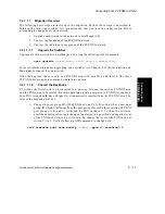
The following basic steps are involved in converting your network. Each of these steps is
described in detail in the following section. It is recommended that you read the entire section
before attempting to change over your network.
1.
Upgrade each switch in the network to ForeThought 5.2.x.
2.
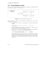
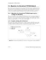
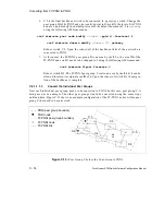
Choose a switch that is at the edge of the network. Convert it to a gateway switch
by changing the default protocol of this switch’s default domain to
gateway
and
reboot the switch. Upon rebooting, this switch will come up with an FT-PNNI node
and a PNNI node. The PNNI node is isolated at this point and does not have any
links attached to it.
3.
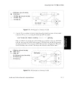
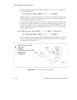
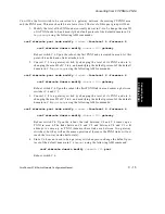
Choose a switch adjacent to the gateway switch, convert it to a gateway switch by
changing its default protocol for the default domain to
gateway
, and reboot this
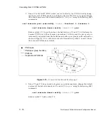
switch. It will come up with a FT-PNNI node and a PNNI node. The link between
the two gateway switches is attached on either end to the respective PNNI nodes.
This link is now the first PNNI link in the network. This single link constitutes a
PNNI area connected by the two gateway switches to the FT-PNNI area. The
FT-PNNI area now contains all the links in the network except the one link
between the two gateways. (It is assumed that there is only one link between the
two gateway switches. If there are multiple links, then all of them will become
PNNI links after this step).
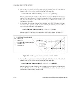
4.
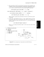
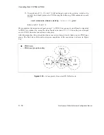
Choose another switch that is adjacent to either one of the two switches already
converted to gateway and repeat step 3. As more and more switches are converted
to be gateways, the PNNI area becomes progressively larger and the FT-PNNI area
becomes smaller.
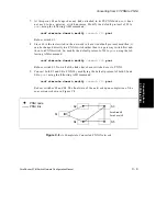
5.
For each gateway, when the last link gets converted from FT-PNNI to PNNI (i.e.,
when the last FT-PNNI switch directly connected to this switch becomes PNNI),
modify the default protocol of the default domain to PNNI and reboot the switch.
By doing this, the FT-PNNI node on this gateway, which no longer has any link,
will be deactivated.
Summary of Contents for forerunner series
Page 6: ......
Page 16: ...TOC 10 ForeRunner ATM Switch Network Configuration Manual Table of Contents ...
Page 20: ...LOF 4 ForeRunner ATM Switch Network Configuration Manual List of Figures ...
Page 22: ...LOT 2 ForeRunner ATM Switch Network Configuration Manual List of Tables ...
Page 30: ...viii ForeRunner ATM Switch Network Configuration Manual Preface ...
Page 144: ...3 58 ForeRunner ATM Switch Network Configuration Manual Configuring an Emulated LAN ...
Page 180: ...6 12 ForeRunner ATM Switch Network Configuration Manual ATM Forum PNNI ...
Page 220: ...9 6 ForeRunner ATM Switch Network Configuration Manual Configuring Timing ...
Page 300: ...D 24 ForeRunner ATM Switch Network Configuration Manual Configuring FramePlus Modules ...
Page 308: ...Acronyms 8 ForeRunner ATM Switch Network Configuration Manual Acronyms ...
Page 346: ...Glossary 38 ForeRunner ATM Switch Network Configuration Manual Glossary ...
Page 352: ...Index 6 ForeRunner ATM Switch Network Configuration Manual Index ...


