C - 24
ForeRunner
ATM Switch Network Configuration Manual
Converting from FT-PNNI to PNNI
5.
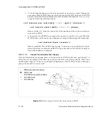
Create a second PNNI node in A.1 with a node index of 2, the peer group ID set to
D, area 3, and level 2 using the following AMI commands:
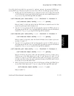
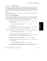
conf atmroute pnni node modify 2 -pgid d -forelevel 2 -forearea 3
conf atmroute domain modify
<domain ID>
pnni
Reboot switch A.1.
6.
Modify the interface on A.1 corresponding to the link to C.1 and attach it to the
newly-created node 2 on A.1 using the following AMI command:
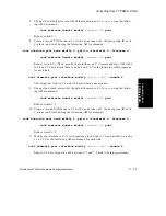
conf atmroute pnni interface modify
<port>
<vpi>
-nodeix 2
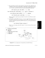
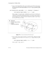
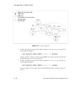
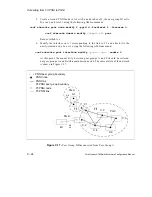
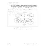
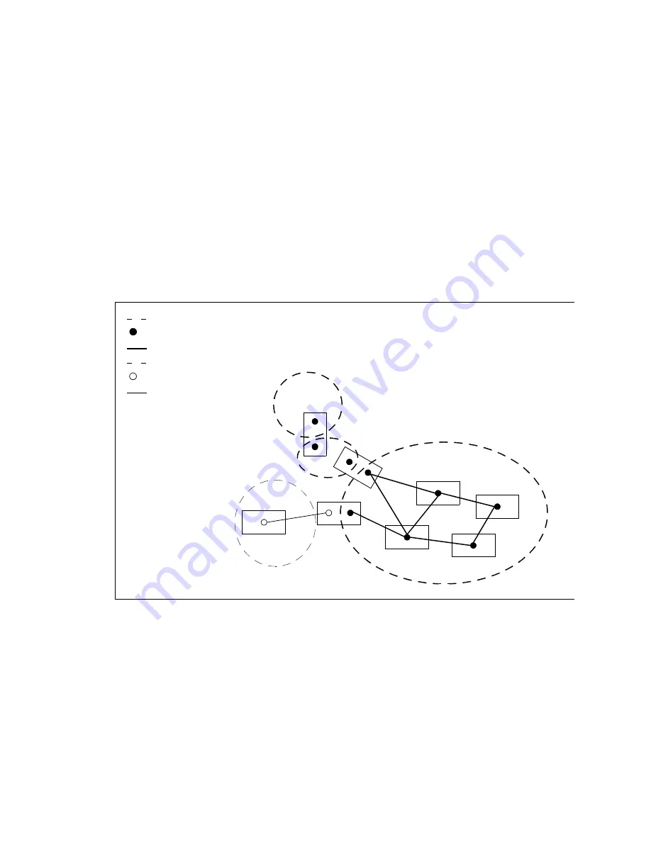
At this point, the connectivity between peer groups A and C should be restored,
but peer groups A and B still remain disconnected. The current state of the network
is shown in Figure C.17.
Figure C.17 -
Peer Group B Disconnected from Peer Group A
C.2
C.4
C.1
C.3
C.6
C.5
A5
L5
PG A
A.1
PG C
PG B
B.1
A4
L4
A6
L5
A3
L2
FT-PNNI node
FT-PNNI peer group boundary
FT-PNNI link
PNNI node
PNNI peer group boundary
PNNI link
Summary of Contents for forerunner series
Page 6: ......
Page 16: ...TOC 10 ForeRunner ATM Switch Network Configuration Manual Table of Contents ...
Page 20: ...LOF 4 ForeRunner ATM Switch Network Configuration Manual List of Figures ...
Page 22: ...LOT 2 ForeRunner ATM Switch Network Configuration Manual List of Tables ...
Page 30: ...viii ForeRunner ATM Switch Network Configuration Manual Preface ...
Page 144: ...3 58 ForeRunner ATM Switch Network Configuration Manual Configuring an Emulated LAN ...
Page 180: ...6 12 ForeRunner ATM Switch Network Configuration Manual ATM Forum PNNI ...
Page 220: ...9 6 ForeRunner ATM Switch Network Configuration Manual Configuring Timing ...
Page 300: ...D 24 ForeRunner ATM Switch Network Configuration Manual Configuring FramePlus Modules ...
Page 308: ...Acronyms 8 ForeRunner ATM Switch Network Configuration Manual Acronyms ...
Page 346: ...Glossary 38 ForeRunner ATM Switch Network Configuration Manual Glossary ...
Page 352: ...Index 6 ForeRunner ATM Switch Network Configuration Manual Index ...

