ForeRunner
ATM Switch Network Configuration Manual
D - 3
Configuring FramePlus Modules
Con
figurin
g
Fram
ePlus
M
odule
s
D.2 Configuring the Module Level
Before configuring any services or PVCs, you should divide the buffer space between the high
and low priority buffers because the PVCs are going to go through these buffers. Cells are read
from the high priority buffer first. Then, after the high priority buffer is emptied, cells are read
from the low priority buffer.
Then you should set the EPD/PPD thresholds for the high and low priority buffers. First, you
need to partition the buffer space.
D.2.1 Dividing the Buffer Space
The FramePlus network module has two priority buffers: high and low. The total, combined
buffering space available is 32,768 cells. The amount of buffering space is split between the
two buffers using
conf
module
fram
setmem
. There are four fixed configuration models for
partitioning the buffer sizes as shown in Table A.1. The default model is highzero.
Table D.1 -
Buffer Models
If you choose highzero, you want all of the buffering space to go in the low priority buffer and
none in the high priority buffer. If you choose high1quarter, then one fourth of the buffering
space goes in the high priority buffer and three fourths goes in the low priority buffer, and so on.
Before you can change the buffer allocation, you must first take the network module out of
service by administering it down as follows:
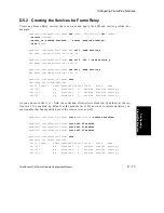
myswitch::configuration module> admin 1d down
Disabling the network module will destroy all
existing connections going through it.
Disable the network module [n]? y
myswitch::configuration module> fram
myswitch::configuration module fram> set 1d high2quarter
The network module comes back up after you make the change so you do not need to use the
conf
module
admin
<module>
up
command.
Model
High Priority Buffer
Low Priority Buffer
highzero
0 cells
32,768 cells
high1quarter
8,192 cells
24,576 cells
high2quarter
16,384 cells
16,384 cells
high3quarter
24,576 cells
16,384 cells
Summary of Contents for forerunner series
Page 6: ......
Page 16: ...TOC 10 ForeRunner ATM Switch Network Configuration Manual Table of Contents ...
Page 20: ...LOF 4 ForeRunner ATM Switch Network Configuration Manual List of Figures ...
Page 22: ...LOT 2 ForeRunner ATM Switch Network Configuration Manual List of Tables ...
Page 30: ...viii ForeRunner ATM Switch Network Configuration Manual Preface ...
Page 144: ...3 58 ForeRunner ATM Switch Network Configuration Manual Configuring an Emulated LAN ...
Page 180: ...6 12 ForeRunner ATM Switch Network Configuration Manual ATM Forum PNNI ...
Page 220: ...9 6 ForeRunner ATM Switch Network Configuration Manual Configuring Timing ...
Page 300: ...D 24 ForeRunner ATM Switch Network Configuration Manual Configuring FramePlus Modules ...
Page 308: ...Acronyms 8 ForeRunner ATM Switch Network Configuration Manual Acronyms ...
Page 346: ...Glossary 38 ForeRunner ATM Switch Network Configuration Manual Glossary ...
Page 352: ...Index 6 ForeRunner ATM Switch Network Configuration Manual Index ...


