1 - 2
ForeRunner
ATM Switch Network Configuration Manual
Configuring PVCs
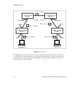
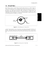
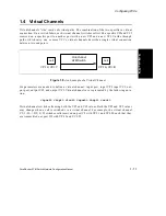
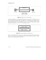
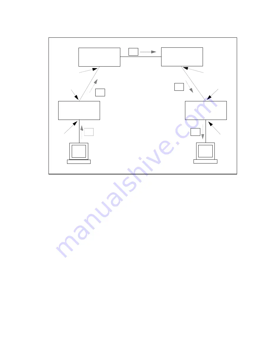
Figure 1.1 -
The Cell
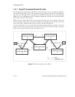
The mappings in an ATM network used to route cells from a source to a destination are gener-
ally referred to as virtual channels and virtual paths. The following sections is to explain how
to create the necessary mappings to establish these virtual paths and virtual channels in a net-
work of ForeRunner ATM switches.
ForeRunner
ATM
ForeRunner
ATM
VPI: 1, VCI: 37
cell
ForeRunner
ATM
ForeRunner
ATM
cell VPI: 1, VCI: 35
cell
VPI: 2, VCI: 33
port A4
port B4
port D1
port B1
port A1
port B3
port C1
Workstation Q
Workstation P
Switch A
Switch B
Switch C
Switch D
port C1
cell
VPI: 0, VCI: 32
VPI: 0, VCI: 36 cell
Summary of Contents for forerunner series
Page 6: ......
Page 16: ...TOC 10 ForeRunner ATM Switch Network Configuration Manual Table of Contents ...
Page 20: ...LOF 4 ForeRunner ATM Switch Network Configuration Manual List of Figures ...
Page 22: ...LOT 2 ForeRunner ATM Switch Network Configuration Manual List of Tables ...
Page 30: ...viii ForeRunner ATM Switch Network Configuration Manual Preface ...
Page 144: ...3 58 ForeRunner ATM Switch Network Configuration Manual Configuring an Emulated LAN ...
Page 180: ...6 12 ForeRunner ATM Switch Network Configuration Manual ATM Forum PNNI ...
Page 220: ...9 6 ForeRunner ATM Switch Network Configuration Manual Configuring Timing ...
Page 300: ...D 24 ForeRunner ATM Switch Network Configuration Manual Configuring FramePlus Modules ...
Page 308: ...Acronyms 8 ForeRunner ATM Switch Network Configuration Manual Acronyms ...
Page 346: ...Glossary 38 ForeRunner ATM Switch Network Configuration Manual Glossary ...
Page 352: ...Index 6 ForeRunner ATM Switch Network Configuration Manual Index ...

