background image

AXEL 

Safety considerations


European  standards  specify  safety  measures  to 
be used on applications with perceived risk. The 
highest rating calls for photobeams and sensitive 
edges, in addition to control panel PSR. 


Ratings for systems in public spaces used by un-
trained  are  higher  than  private  gates  operated 
by  trained.  Autonomous  devices  such  as  timers 
and vehicle detectors add a level of risk. 
 
The  safety  tutorial  at  the  end  of  this  manual  is 
dedicated  to  defining  ‘risk’.  The  design  and 
layout  of  a  gate  can  eliminate  many  risks, 
avoiding  the  need  for  more  safety  devices.  
Control  panel  electronic  measures  do  not 

make 

the system compliant on their own.  

Double leaf set 

 

2x motor casings 

 

2x motor gearboxes 

 

Control panel with remote receiver 

 

2x IR safety photo-beams 

 

2x remote controls 


Installer responsibility 

An  automated  gate  is  a  machine  that  must 
comply  with  the  EU  Machines  directive.  There 
are many aspects of compliance that ensure the 
gate is safe to users and public. ‘Automatic gate’ 
signs  are  required  on  both  sides  of  the  gate 
warning against risk of contact injury.  


The  installer  must  prepare  a  handover  pack  to 
include  details  of  the  installation,  a  user  guide 
and a risk statement. Much of that information is 
included  in  this  manual,  along  with  guides  to 
indentify site specific risks and gate attributes. 
Good practice is essential to safety & reliability. 
Note outdoor installations electrical standards.  


Homeowner responsibility


It  is  the  responsibility  of  the  owner  to  ensure 
only  trained  people  operate  the  gate,  and  they 
are aware of potential gate hazards. Owners are 
responsible  for  injury  resulting  from  failure  to 
meet the requirements in this manual.  


The  person  operating  the  gate  must  take 
responsibility for the safety of any person within 
the  hazard  area.  Never  let  children  play  near 
gates in motion.  


Gates  must  be  robust,  well  maintained,  and  on 
clean level  ground.  Keep  the gate area clear of 
objects.  Have  the  gate  properly  maintained  and 
repaired  by  qualified  personnel  to  maintain  the 
legal safety requirements.  


Summary of Contents for AXEL F730

Page 1: ...www forematic com Underground gate opener AXEL AXEL F730 installation...

Page 2: ...nd up to date Technical Specifications Supply volt age 220 240Vac Motor power 100W 24Vdc Supply rating 2 5A 50 60Hz Motor torque 250Nm max Standby power 10W Motor insula tion IP67 Ambient temp 20 to 7...

Page 3: ...compliance that ensure the gate is safe to users and public Automatic gate signs are required on both sides of the gate warning against risk of contact injury The installer must prepare a handover pac...

Page 4: ...s The most common D requires the gate to be off centre and therefore will require a safety edge to protect the pinch hazard E is on centre but leaves a sight gap or you need to cope with a rear hung g...

Page 5: ...ently fill the casement then fill the soakaway Consider a surface drain Wood swells when it absorbs moisture A gap between gate boards and between gate leaves is essential Any sight gap between leaves...

Page 6: ...or with steel post reinforcement That is a decision beyond the scope of this manual Two concrete bases are required for the piers set at precisely the same level Level off 170mm below road level to g...

Page 7: ...ss control it is normally fitted to the left pier because that is the side visitors get out of their vehicles Height is typically 1 5m Leave a suitable duct access hole Ducts will run either to the co...

Page 8: ...you need the gate to open less you can fit an addition ground stop Fit the stub axle plate and stop plate over the exposed studs in the upper shelf then fix with the locking nuts Fig 12b Motor arms M...

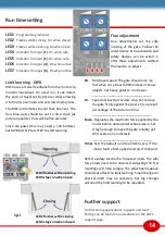
Page 9: ...ter the panel through glands Running the cables behind the PCB keeps the limited space tidy It is better to hide cables than cut them too short Mark all cables The wiring plan below shows individual c...

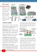
Page 10: ...Move the green wire to D for single leaf door opening Remotes can be set for these two functions See user instructions SAFETY DEVICES F C or E C There two inputs are for safety devices Input F preven...

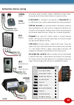
Page 11: ...o work during the day could be viable free entry device for a commercial property Keypads are useful for friends family or trusted delivery drivers This keypad can accept many codes and some for singl...

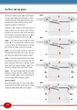
Page 12: ...hinge position is on the pier corner so finger traps are less likely Fig21 An safety edge has been added to the gate leaf that closes last There are now two devices on F wired as Fig26 or Fig27 Fig22...

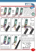
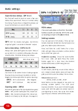
Page 13: ...nd of the gate E or F power Beam Fig 27 One DRI edge on on a pier power Beam Fig 28 Wiring 2 DRI s Yellow NC Blue Com Black Gnd Red Supply power Open Timer A wired switch or timer can hold a gate open...

Page 14: ...y 100 010 110 001 101 011 111 5s 15s 20s 60s 65s 75s 80s Delay 2s 3s 4s 5s DIP 1 2 opening 00 10 01 11 DIP 3 4 closing 00 10 01 11 PCB buttons There are two buttons on the PCB The CODE button is used...

Page 15: ...ial for force test limits The safe force limits need to be observed Adjusting the first 3 settings will help comply The adjustments above should not affect the limit learning Small changes in physical...

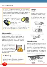
Page 16: ...p to maintain safety Our website PICO support page has fault finding support You can save up to 50 remotes There are two remote channels Pedestrian channel opens one gate only Main opens both You will...

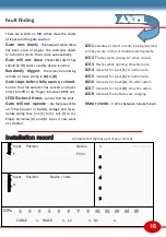
Page 17: ...ords Activation Input Position Device code G Fault finding There are 8 LED s on RIO X that show the states of inputs and the gate position Gate runs slowly This happens when there has been a loss of p...

Page 18: ...de of Practice can be found at www dhfonline org uk Force testing EN12445 explains the method of testing the impact forces of a gate The crux is a graph of acceptable forces from the point of impact S...

Page 19: ...of Practice Draw in or Shear Gaps where a body part could be drawn in are not allowed Limbs have different nominal sizes Finger gaps need to be less than 8mm D2 arms less than 100mm etc A solid infil...

Page 20: ...ot accept costs for dismantling installation or for carriage Parts replaced under warranty are the property of the warrantor The warranty period for Radio Equipment is 24 months The period for replace...

Reviews: