background image

 8 


BATTERY 

LEAK TEST 

To prevent fire or explosion hazard when testing for a leak: 

1.  Always perform the leak test as described below before lighting this appliance or each time the cylinder is 

connected for use.


2.  Do not smoke or allow other sources of ignition in the area while conducting a leak test.


3.  Conduct the leak test outdoors in a well-ventilated area.


4.  Do not use matches, lighters or a flame to check for leaks.


5.  Do not use this appliance until any and all leaks are corrected. If you are unable to stop a leak, disconnect 

the propane supply. Call a gas appliance service shop or your local propane gas supplier.


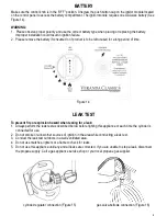
cylinder-regulator connection (Figure 15)


gas valve-bellows connection (Figure 16)


Figure 14


Make sure the control knob is in the “OFF” position. Unscrew the push button cap on the ignitor module located 
on the control panel to access the battery compartment. The ignitor module requires one AAA size battery (See 
Figure 14). 


WARNING:   

1.  Please observe proper polarity and use the correct battery type when placing or replacing the battery.  
      Improper installation could result in ignition failure. 
2.   Please remove the battery if consumed or if product is to be left unused for a long period of time.


Summary of Contents for FIGS545GFPB

Page 1: ...onsumer Consumer Keep these instructions for further reference Questions Problems Missing Parts Before returning to your retailers contact Foremost Groups Customer Relations Department toll free number at 1 800 443 1410 USA between the hours of 8 30 am and 5 00 pm EST Monday thru Friday or fax your request to 973 428 8026 or email us at customerservice foremostgroups com ...

Page 2: ...control compartment burners and circulating air passageways of the appliance are kept clean 11 CAUTION The propane gas pressure regulator provided with this appliance must be used This regulator is set for an outlet pressure of 11 inches water column 12 DO NOT burn solid fuels in this appliance 13 This outdoor gas appliance is for Outdoor Use ONLY 14 This outdoor gas appliance is not intended to b...

Page 3: ...lar to protect the cylinder valve 7 This appliance shall be used only outdoors in a well ventilated space and shall not be used in a building garage or any other enclosed space 8 When this appliance is not in use the gas must be turned off at the supply cylinder 9 Storage of this appliance indoors is permissible only if the cylinder is disconnected and removed from the Appliance 10 Cylinders must ...

Page 4: ...t parts 2 Fix the Table Top Frame A onto the Base Assembly B with Stud E Washer F Spring washer G and Nut H screw the Nut H tightly by using the Wrench I see Figure 3 Hardware Used E Stud 5 16 30 x 4 F Washer x 4 G Spring washer x 4 H Nut x 4 PART DESCRIPTION PICTURE QUANTITY E Stud 5 16 30 4 F Washer 4 G Spring wahser 4 H Nut 5 16 4 I Wrench 1 Figure 3 A B C E F G H D PART DESCRIPTION QUANTITY A ...

Page 5: ... pieces and can be swallowed by children 5 Open the door place the gas cylinder into the cylinder holder connect the regulator screw the black handle clockwise to tighten turn the black handle counterclockwise to remove The hose must point down The knob on the control panel is turned all the way to the OFF position when the fire pit is NOT in use Make sure the hose is routed through the two U ring...

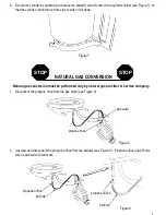
Page 6: ...s conversion must be performed only by natural gas provider or service company 1 Disconnect the propane hose from the gas valve see Figure 8 Figure 8 2 Unscrew and disconnect the propane orifice from the bellows see Figure 9 Propane orifice dia2 15mm size is painted with red mark Figure 9 propane hose gas valve propane orifice bellows propane orifice bellows NATURAL GAS CONVERSION STOP STOP ...

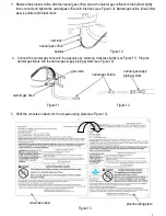
Page 7: ...piping system see Figure 12 Figure 12 Figure 13 3 Replace the propane orifice with the natural gas orifice screw the natural gas orifice with the bellows tightly then connect and tighten the natural gas orifice with inlet tube see Figure 10 Natural gas orifice dia4 30mm size is painted with black mark natural gas orifice inlet tube bellows 5 Stick the conversion label onto the propane rating plate...

Page 8: ...le to stop a leak disconnect the propane supply Call a gas appliance service shop or your local propane gas supplier cylinder regulator connection Figure 15 gas valve bellows connection Figure 16 Figure 14 Make sure the control knob is in the OFF position Unscrew the push button cap on the ignitor module located on the control panel to access the battery compartment The ignitor module requires one...

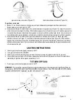
Page 9: ... are secure If bubbles appear the connection has the leak disconnect reconnect perform another leak check If you continue to see bubbles after several attempts the part is defective and should replace the part inlet tube bellows connection Figure 18 gas valve hose connection Figure 17 LIGHTING INSTRUCTIONS 1 Push in gas control knob slightly and turn to OFF 2 Turn gas control knob the ON MIN 3 Pus...

Page 10: ...ssible blockage include 1 Gas odor with extreme yellow tipping of flame 2 Fire pit does NOT reach the desired temperature 3 Fire pit flame is excessively uneven 4 Fire pit makes popping noises 5 Spiders and insects can nest in burner or orifice This dangerous condition can damage fire pit and render it unsage for use Clean burner holes by using a heavy duty pipe clearer Compressed air may help cle...

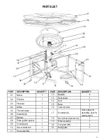
Page 11: ...ntrol panel 1 10 Gas control knob 1 11 Hose assembly 1 PART DESCRIPTION QUANTITY 12 Bakelite 4 13 Heat shield 1 14 Door 1 15 Base 1 16 Table top frame 1 17 Porcelain tile 10pcs 8pcs for assembly 2pcs for replacement 18 Gas cylinder protective ring 1 19 Wheel assembly 1 20 Foot glider M8 4 21 Rating plate 1 22 R 21 14 01 06 10 08 11 04 05 07 15 09 02 03 12 13 17 18 19 20 16 ...

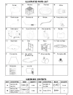
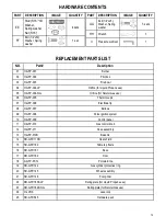
Page 12: ...QUANTITY CC Bolt M4 10 Nut M4 8 sets DD Screw T5 15 4 22 04 Burner 01 Pilot box 02 03 Fire bowl Electrode tip Thermocouple Orifice Bellows Pulse ignition system Control panel Bakelite Hose assembly Gas control knob Heat shield Door Base 05 06 07 08 09 10 11 12 13 14 15 16 17 18 Gas cylinder protective ring 19 20 21 Table top frame Porcelain tile Wheel assembly Foot glider M8 Rating plate ...

Page 13: ...H GFP 004 NG Orifice for Natural Gas use 06 H GFP 005 Thermocouple 07 H GFP 006 Electrode tip 08 H GFP 007 Bellows 09 H GFP 008 Pulse ignition system 10 H GFP 009 Control panel 11 H GFP 010 Gas control knob 12 H GFP 011 Hose assembly 13 H GFP 012B Bakelite 14 SR GFP 110B Heat shield 15 SR GFP 160 Table top frame 16 SR GFP 161 Base 17 SR GFP 162 Door 18 X GFP PCTL Porcelain tile 19 SR GFP 144 Gas c...

Page 14: ...models or items purchased in an as is condition freight damage firepit damaged by acts of nature vandalism fire abuse lack of proper care and maintenance or improper assembly straps and normal fading or discoloration from exposure to elements oils spills fluids or chemicals Table top against breakage hardware against corrosion or rusting buckling or splitting of tubing resulting from exposure to w...

Reviews: