-14-
FES101E6
User Manual
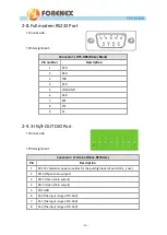
2-8.
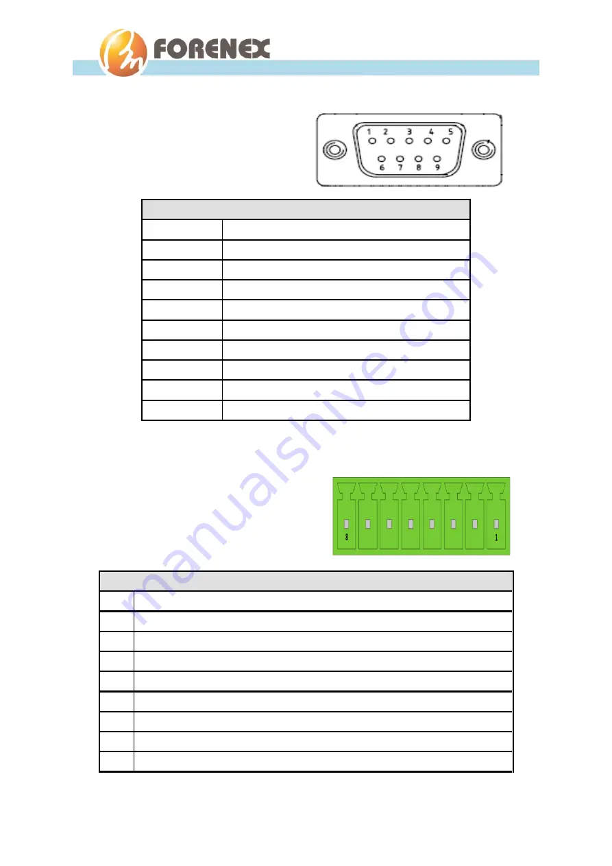
Full modem RS232 Port
On rear side.
Pin Assignment.
2-9.
3-IN/3-OUT DIO Port
On rear side.
Pin Assignment.
Connector: ( DTE-DB9/Male /Black)
Pin number
Description
1
DCD
2
RXD
3
TXD
4
DTR
5
COM-GND
6
DSR
7
RTS
8
CTS
9
RI
Connector: ( Terminal Block-8P/Male )
Pin
Description
1
EXT-VCC (External power provides for the pull-high level of pin DO-0,1,2 use)
2
DO-0 (
O
pen Drain output)
3
DO-1 (Open Drain output)
4
DO-2 (Open Drain output)
5
DIO-GND
6
DI-0 (the input range of 5V-36V)
7
DI-1 (the input range of 5V-36V)
8
DI-2 (the input range of 5V-36V)
Summary of Contents for FES101E6
Page 4: ...4 FES101E6 User Manual 3 2 2 To control DIO Ports 20 3 2 3 To control Comport Mode 21...
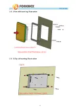
Page 9: ...9 FES101E6 User Manual 1 3 2 Panel Mounting Illustration 1 3 3 Clips Mounting Illustration...
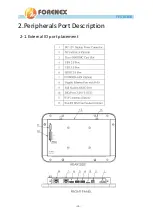
Page 10: ...10 FES101E6 User Manual 2 Peripherals Port Description 2 1 External IO port placement...


